Low Differential Pressure Transducer
Low Differential Pressure Transducer
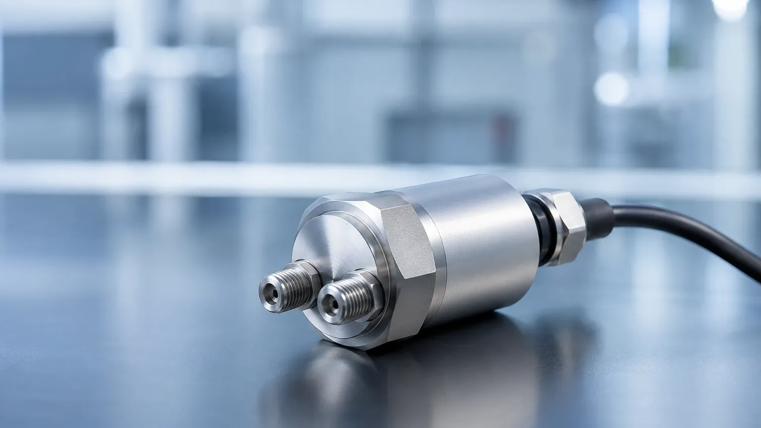
In the field of industrial process control and fluid dynamics, the ability to measure minute differences in pressure between two points is critical for maintaining system integrity, safety, and efficiency. A low differential pressure transducer is a specialized instrument designed to detect and convert very small pressure variations—often in the range of a few pascals (Pa) to several kilopascals (kPa)—into a standardized electrical signal. These devices are foundational in applications ranging from cleanroom monitoring and HVAC airflow control to sensitive hydrostatic level measurement in pressurized vessels.
Understanding the technical nuances of these instruments is essential for engineers and procurement professionals. This guide explores the underlying measurement principles, selection criteria, and practical installation strategies for integrating low differential pressure transducers into industrial environments.
Measurement Principles of Low Differential Pressure
Before selecting a specific model, it is vital to understand how these sensors translate physical force into data. The core of a differential pressure (DP) transducer is the sensing element, typically a diaphragm that separates two pressure ports: the high-pressure (HI) side and the low-pressure (LO) side.
1. Variable Capacitance
Variable capacitance is one of the most common technologies used for low-range measurements. The sensing element consists of a metallic or ceramic diaphragm positioned between two fixed plates. As the pressure difference changes, the diaphragm deflects, altering the capacitance between it and the plates. Because the diaphragm movement required to change capacitance is extremely small, this technology is highly sensitive and stable, making it ideal for "low" ranges (e.g., 0 to 25 Pa or 0 to 0.1 inches of water column).
2. Piezoresistive Silicon
In this design, strain gauges are diffused into a silicon diaphragm. When the diaphragm bends under pressure, the electrical resistance of the gauges changes (the piezoresistive effect). While silicon sensors are highly accurate and cost-effective, they often require sophisticated temperature compensation to maintain accuracy in low-pressure ranges, as thermal expansion can mimic pressure changes.
3. LVDT (Linear Variable Differential Transformer)
Though less common in ultra-miniature formats, LVDT-based transducers use a diaphragm linked to a magnetic core. As the diaphragm moves, the core shifts within a transformer, changing the output voltage. This is a robust technology often used in heavy industrial applications where vibration resistance is paramount.
The Role of Low DP Transducers in Level Measurement
While often associated with airflow, low differential pressure transducers are indispensable for liquid level measurement, particularly in closed tanks or bubbler systems. The relationship is governed by the hydrostatic pressure formula:
P = ρ × g × h
* P: Hydrostatic pressure
* ρ (rho): Density of the liquid
* g: Gravitational acceleration (approx. 9.81 m/s²)
* h: Height of the liquid column
In a pressurized tank, a standard pressure gauge at the bottom would measure both the liquid weight and the gas pressure above it. By using a low differential pressure transducer, the "LO" port is connected to the top of the tank (the gas space) and the "HI" port to the bottom. The device subtracts the head pressure of the gas, leaving only the pressure exerted by the liquid column. For shallow tanks or liquids with low density, the resulting pressure signal is very small, necessitating a high-sensitivity low DP transducer.
Key Evaluation Criteria for Selection
Choosing the wrong transducer can lead to signal noise, frequent recalibration, or premature sensor failure. Engineers should evaluate the following factors:
Full-Scale Range and Turndown Ratio
The transducer should be selected so that the maximum expected pressure occupies 75% to 90% of its full-scale range. However, many modern transducers offer a "turndown ratio," allowing a 1,000 Pa sensor to be calibrated for a 200 Pa range without significant loss of accuracy.
Static Pressure (Line Pressure)
It is a common mistake to confuse differential pressure with static pressure. A transducer might be measuring a tiny difference of 50 Pa, but both ports might be under a base pressure of 10 bar (1,000,000 Pa). The sensor must be rated to withstand the maximum static pressure of the system without the diaphragm deforming or the housing bursting.
Wetted Materials and Media Compatibility
The "wetted parts"—the components in direct contact with the fluid—must be chemically compatible with the process. For water treatment or general HVAC, 316L stainless steel is standard. For corrosive chemicals, materials like Hastelloy C, Monel, or PTFE coatings may be required.
Accuracy and Long-Term Stability
Accuracy is typically expressed as a percentage of Full Scale (FS). For low-pressure applications, "Zero Drift" is the most significant concern. Because the signal is so small, even a tiny shift in the sensor’s zero point due to temperature or aging can result in a large percentage error.
Practical Selection Table
| Application Type | Typical Pressure Range | Recommended Sensor Tech | Key Priority |
| :— | :— | :— | :— |
| Cleanroom Monitoring | 0 to 60 Pa | Variable Capacitance | High Sensitivity & Stability |
| Bubbler Level Systems | 0 to 5,000 Pa | Piezoresistive | Clog Resistance & Accuracy |
| HVAC Duct Flow | 0 to 250 Pa | Silicon Micro-machined | Cost-effectiveness |
| Chemical Tank Level | 0 to 20,000 Pa | Diaphragm Seal (DP) | Chemical Compatibility |
Installation Considerations
Proper installation is as important as the hardware itself. For a low differential pressure transducer, the following guidelines ensure reliable data:
1. Orientation Sensitivity: In very low ranges, the weight of the diaphragm itself can affect the reading. Always mount the transducer in the orientation specified by the manufacturer (usually vertical). If it must be mounted horizontally, ensure the device is zeroed in that specific position.
2. Impulse Piping: The tubes connecting the process to the transducer (impulse lines) should be as short as possible. For liquid applications, the lines should slope upward toward the tank to allow gas bubbles to escape. For gas applications, they should slope downward to allow condensate to drain.
3. Manifolds: Use a 3-valve or 5-valve manifold. This allows the operator to isolate the sensor from the process and equalize the pressure between the HI and LO ports for zero-point calibration without removing the device from the line.
4. Environmental Protection: While the process media is handled by the ports, the housing must protect the electronics from moisture and dust. Look for IP65 or IP67 ratings for industrial environments.
Common Risks and Limitations
Despite their precision, low differential pressure transducers face specific challenges:
* Overpressure Events: A sudden spike in pressure on one side (e.g., a valve slamming shut) can rupture a sensitive low-pressure diaphragm. Ensure the transducer has internal overpressure protection or use external snubbers.
* Temperature Effects: Because these sensors are highly sensitive, thermal expansion of the internal components can cause "thermal drift." In outdoor installations, heated enclosures or insulated jackets are often necessary.
* Condensation: In gas flow applications, if the gas cools within the impulse lines, moisture can condense. This liquid can block the lines or damage the sensor. Drip legs or heated trace lines are common solutions.
Frequently Asked Questions (FAQs)
Q: Can I use a high-pressure DP transducer for low-pressure measurements?
A: Generally, no. While you can technically calibrate a 100 kPa sensor to read 1 kPa, the signal-to-noise ratio will be extremely poor, and the accuracy will drop significantly. It is always better to use a sensor designed for the specific range.
Q: What is the difference between a pressure transmitter and a transducer?
A: In common industrial parlance, a *transducer* provides a voltage output (e.g., 0-5V), while a *transmitter* provides a current output (e.g., 4-20mA). Current signals are preferred for long-distance transmission as they are less susceptible to electrical noise.
Q: How often should a low DP transducer be calibrated?
A: For critical applications like cleanrooms or hazardous chemical level monitoring, annual calibration is standard. However, checking the "zero" point every six months is recommended to account for sensor aging.
Conclusion and Next Steps
Selecting a low differential pressure transducer requires a balance between sensitivity and durability. By understanding the hydrostatic principles and the specific demands of your media, you can ensure a measurement solution that provides long-term reliability. For those integrating these sensors into broader automation systems, confirming the electrical output (HART, Modbus, or 4-20mA) and the physical process connections is the final step before procurement.
For more detailed technical specifications and to explore a wide range of industrial measurement instruments, you may review product options and application support to find the ideal fit for your project requirements.