Volumetric Flow Sensor
Volumetric Flow Sensor
In industrial process control, the ability to quantify the movement of fluids is fundamental to operational efficiency, safety, and billing accuracy. A volumetric flow sensor is a device designed to measure the volume of fluid—liquid or gas—that passes through a specific cross-sectional area per unit of time. Unlike mass flow meters, which measure the weight or mass of the fluid, volumetric sensors focus on the space the fluid occupies, typically expressed in cubic meters per hour (m³/h), liters per minute (L/min), or gallons per minute (gpm).
For engineers and plant managers, selecting the correct volumetric flow sensor requires a deep understanding of fluid dynamics, installation constraints, and the specific physical properties of the medium being measured. This guide provides a technical overview of volumetric flow measurement principles, technology types, and practical selection criteria for industrial applications.
Fundamental Principles of Volumetric Flow Measurement
Volumetric flow measurement is generally based on one of three physical approaches: velocity measurement, differential pressure, or direct volume displacement. Understanding these principles is the first step in determining which sensor technology is appropriate for a given process.
Velocity-Based Measurement
The most common method for determining volumetric flow is measuring the velocity ($v$) of the fluid and multiplying it by the known cross-sectional area ($A$) of the pipe or channel. The mathematical relationship is expressed as:
$$Q = A \times v$$
Where $Q$ is the volumetric flow rate. Technologies such as ultrasonic, electromagnetic, and turbine flow meters rely on this principle. The accuracy of these sensors is highly dependent on the flow profile—the distribution of velocity across the pipe diameter. A fully developed, symmetrical flow profile is essential for precise measurement.
Differential Pressure (DP)
Differential pressure sensors operate on Bernoulli’s principle, which states that an increase in the speed of a fluid occurs simultaneously with a decrease in static pressure. By placing a restriction (like an orifice plate or Venturi tube) in the flow path, a pressure drop is created. The square root of this pressure difference is proportional to the flow rate. While robust, these systems introduce a permanent pressure loss into the piping system.
Positive Displacement (PD)
Positive displacement meters measure flow by trapping a fixed volume of fluid and moving it through the meter. Each "pocket" of fluid is counted, providing high accuracy even in high-viscosity applications. Common examples include gear meters and oscillating piston meters. These are mechanical in nature and are often used for oil and gas custody transfer.
Primary Technologies for Volumetric Flow Sensors
Industrial applications demand different sensor architectures based on the environment and the fluid's characteristics. Below are the most prevalent technologies used in modern B2B environments.
Electromagnetic Flow Meters (Magmeters)
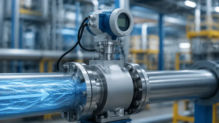
Magmeters operate based on Faraday’s Law of Electromagnetic Induction. When a conductive liquid flows through a magnetic field generated by the sensor, it induces a voltage proportional to its velocity.
- Best for: Conductive liquids, slurries, and wastewater.
- Advantages: No moving parts, zero pressure drop, and high reliability.
- Limitations: Cannot measure non-conductive fluids like oils or deionized water.
Ultrasonic Flow Meters
Ultrasonic sensors use sound waves to determine flow velocity. There are two primary types: Transit-time and Doppler. Transit-time sensors measure the time difference between signals sent upstream and downstream. Doppler sensors measure the frequency shift caused by reflections off bubbles or particles in the fluid.
- Best for: Clean liquids (Transit-time) or aerated/dirty liquids (Doppler).
- Advantages: Non-intrusive (clamp-on models available), no pressure drop.
- Limitations: Requires specific pipe materials and may be affected by acoustic noise.
Turbine Flow Meters
These sensors utilize a multi-bladed rotor suspended in the flow stream. The fluid's movement causes the rotor to spin at a speed proportional to the flow rate. The rotations are detected electronically to calculate volume.
- Best for: Clean, low-viscosity fluids at high pressure.
- Advantages: High accuracy and fast response time.
- Limitations: Moving parts are subject to wear; sensitive to viscosity changes.
Open Channel Flow: The Level-Flow Relationship
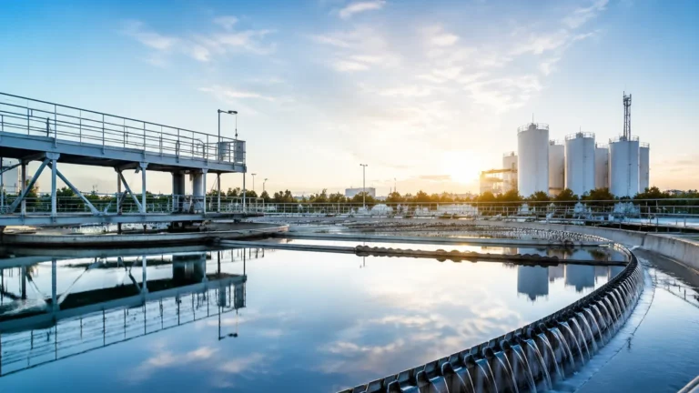
In many water treatment and irrigation applications, fluids are not contained within a full pipe but flow through open channels, flumes, or weirs. In these scenarios, a volumetric flow sensor often consists of a level measurement instrument paired with a primary flow element.
By measuring the head (level) of the liquid behind a weir or within a flume, the volumetric flow rate can be calculated using standardized formulas (e.g., the Kindsvater-Carter equation for weirs). Welk’s expertise in level measurement provides a critical foundation here; radar level meters and ultrasonic level sensors are frequently deployed as the sensing component in these flow systems. Because radar is non-contact, it is unaffected by surface debris or steam, making it an ideal choice for accurate open-channel volumetric calculations.
For those evaluating instrumentation for complex industrial setups, reviewing the Main Page of specialized manufacturers can provide insights into how level and flow technologies integrate within a unified control architecture.
Selection Criteria and Comparison Table
Choosing a volumetric flow sensor involves balancing performance requirements against total cost of ownership. The following table summarizes the key considerations for the most common industrial technologies.
| Technology | Typical Accuracy | Fluid Conductivity | Viscosity Limit | Pressure Drop | Maintenance Level |
| :— | :— | :— | :— | :— | :— |
| Electromagnetic | ±0.5% | >5 μS/cm | Medium | None | Low |
| Ultrasonic | ±1.0% | Any | Low to Medium | None | Low |
| Turbine | ±0.25% | Any | Low | High | Medium |
| Orifice Plate | ±2.0% | Any | Low | High | Medium |
| Radar (Open Channel) | ±1-2% | Any | N/A | None | Low |
Key Evaluation Factors
1. Fluid Properties: Is the medium corrosive, abrasive, or conductive? Does it contain solids?
2. Flow Range (Turndown Ratio): What are the minimum and maximum expected flow rates? Some sensors lose accuracy at the bottom end of their range.
3. Operating Environment: Are there extreme temperatures or pressures? Is the area rated as hazardous (ATEX/IECEx)?
4. Installation Footprint: Is there enough straight pipe run to satisfy the sensor's requirements?
Installation Requirements and Best Practices
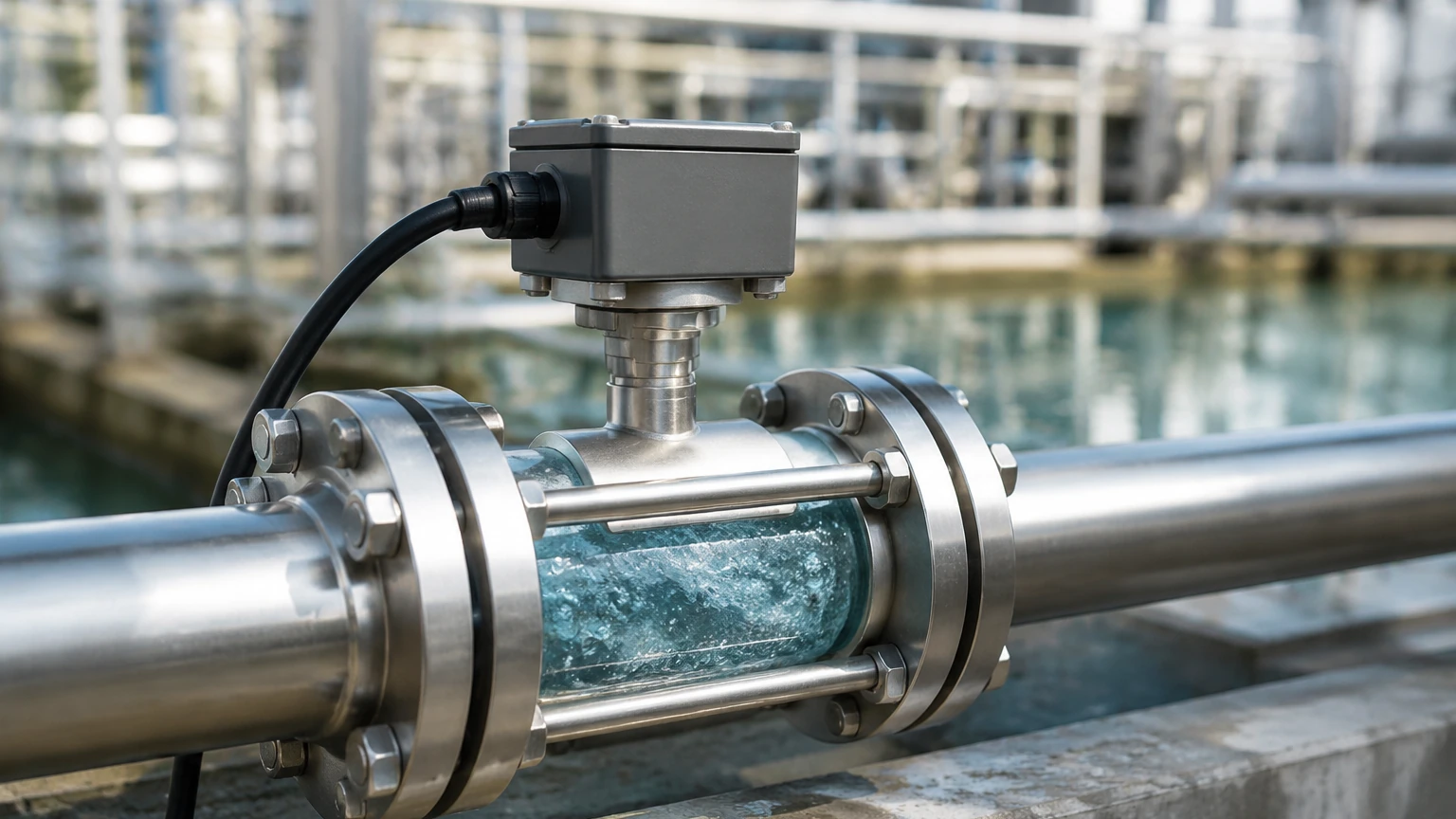
Even the most advanced volumetric flow sensor will fail to deliver accurate data if installed incorrectly. Engineers must adhere to strict installation guidelines to ensure a stable flow profile.
Straight Pipe Runs
Most velocity-based sensors require a minimum length of straight pipe before (upstream) and after (downstream) the sensor. This is typically expressed in pipe diameters (D). A common requirement is 10D upstream and 5D downstream. Elbows, valves, and pumps create turbulence that can skew readings if the sensor is placed too close to these disturbances.
Pipe Orientation and Filling
To ensure accuracy, the pipe must be completely full of liquid. For this reason, volumetric flow sensors are ideally installed in vertical pipes with upward flow. If installed horizontally, the sensor should not be at the highest point of the system, where air pockets can accumulate, nor at the lowest point, where sediment might settle.
Grounding and Interference
For electromagnetic flow meters, proper grounding is essential to prevent stray electrical currents from interfering with the low-voltage signal generated by the flow. Similarly, ultrasonic sensors must be shielded from high-frequency vibration or acoustic noise from nearby machinery.
Limitations and Common Application Risks
While volumetric flow sensors are versatile, they are not universal solutions. Users should be aware of the following risks:
- Viscosity Sensitivity: Many sensors, particularly turbine and DP meters, are calibrated for specific viscosities. If the fluid thickens due to temperature drops, the sensor may over-read or under-read significantly.
- Aeration and Cavitation: Bubbles in a liquid line can cause ultrasonic transit-time sensors to lose signal or cause magmeters to report erratic volumes. Proper system venting is required.
- Scaling and Coating: In chemical or wastewater applications, buildup on the internal walls of the sensor or on electrodes can insulate the signal, leading to drift. Non-contact methods, such as radar level sensors used for open channel flow, mitigate this risk.
- Reynolds Number Dependencies: Most flow meters are designed for turbulent flow (high Reynolds numbers). In low-flow, laminar conditions, the accuracy of many volumetric sensors degrades rapidly.
Frequently Asked Questions (FAQ)
Q: How does a volumetric flow sensor differ from a mass flow meter?
A: A volumetric sensor measures the space the fluid occupies (m³), while a mass flow meter (like a Coriolis meter) measures the actual weight (kg). Since volume changes with temperature and pressure—especially in gases—mass flow is often preferred for high-precision chemical reactions or billing, whereas volumetric flow is standard for general process control and water management.
Q: Can I use a volumetric flow sensor for steam?
A: Yes, but with caution. Differential pressure meters and vortex shedding meters are commonly used for steam. However, because steam is compressible, you must also measure temperature and pressure to calculate the "compensated" volumetric flow or mass flow.
Q: What is the "Turndown Ratio"?
A: It is the ratio of the maximum flow the sensor can measure to the minimum flow where it maintains its rated accuracy. For example, a 10:1 turndown ratio means a sensor rated for 100 m³/h can accurately measure down to 10 m³/h.
Q: Do non-contact sensors require less maintenance?
A: Generally, yes. Sensors like ultrasonic clamp-on meters or radar level-to-flow systems do not touch the process media, meaning they are not subject to corrosion, clogging, or mechanical wear. This significantly reduces long-term maintenance costs in harsh industrial environments.
Conclusion
Selecting a volumetric flow sensor is a technical decision that impacts the long-term reliability of an industrial process. By understanding the underlying physics—whether it be electromagnetic induction, ultrasonic transit time, or hydraulic head in open channels—engineers can match the technology to the specific demands of the fluid and the environment.
For comprehensive technical specifications and to explore a range of measurement solutions suitable for water treatment, chemical processing, and industrial automation, professionals are encouraged to consult specialized engineering resources. Exploring the Main Page of an established manufacturer like Welk can provide the necessary data sheets and application support to ensure the chosen instrument meets the rigorous standards of modern industry.