Radar Level Transmitter Installation Guide
Radar Level Transmitter Installation Guide
In the realm of industrial process control, the accuracy of level measurement is a cornerstone of operational safety and efficiency. Among the various technologies available, radar level measurement has emerged as a premier solution due to its non-contact nature and high precision. However, the performance of even the most advanced Radar Level Meters is heavily dependent on correct physical integration. This radar level transmitter installation guide provides a comprehensive technical framework for engineers and plant managers to ensure optimal device performance across diverse industrial environments.
Understanding Radar Measurement Principles
Before proceeding with installation, it is essential to understand how radar technology interacts with the process environment. Industrial radar level transmitters primarily utilize two methods: Pulse Radar and Frequency Modulated Continuous Wave (FMCW).
Pulse Radar
Pulse radar systems emit a microwave signal toward the material surface in short bursts. The device measures the "time of flight"—the duration it takes for the pulse to travel to the surface and return to the sensor. Since the speed of light is constant, the distance is calculated based on this time interval. Pulse radar is often favored for its lower power consumption and suitability for simpler liquid level applications.
FMCW (Frequency Modulated Continuous Wave)
FMCW radar, which is increasingly common in high-precision 80GHz transmitters, emits a continuous signal with a constantly changing frequency. The difference in frequency between the emitted signal and the received echo is proportional to the distance. This method offers superior resolution and signal-to-noise ratios, making it ideal for measuring solids, powders, or liquids in turbulent conditions.
The Role of Dielectric Constant (εr)
The reflectivity of the target material is governed by its dielectric constant (εr). Materials with high dielectric constants, such as water (εr ≈ 80), reflect radar waves strongly. Conversely, hydrocarbons and dry solids often have low dielectric constants (εr < 2), which result in weaker return signals. Understanding the εr of your medium is the first step in selecting the correct antenna type and sensitivity settings.
Selection Criteria for Radar Instrumentation
Choosing the right instrument involves balancing frequency, antenna design, and process conditions. This selection directly impacts the complexity of the radar level transmitter installation guide requirements for a specific site.
| Feature | 26GHz Radar | 80GHz Radar | Guided Wave Radar (GWR) |
| :— | :— | :— | :— |
| Beam Angle | 8° to 20° (Wider) | 3° to 8° (Narrow) | N/A (Follows Probe) |
| Best Use Case | Large storage tanks, liquids | Narrow silos, agitators, solids | Low εr fluids, interface |
| Nozzle Sensitivity | Moderate | Low (Easier to install) | High (Requires bypass/stilling well) |
| Accuracy | ±3 mm to ±5 mm | ±1 mm | ±2 mm |
| Max Range | Up to 30m – 70m | Up to 120m | Up to 30m – 75m |
Comprehensive Radar Level Transmitter Installation Guide
Successful installation requires adherence to geometric constraints and process-specific variables. The following guidelines apply to most non-contact radar installations.
1. Optimal Mounting Position
The horizontal placement of the transmitter on the tank roof is critical.
* Distance from Wall: The sensor should ideally be installed at a distance of 1/4 to 1/6 of the tank diameter from the side wall. Installing too close to the wall (less than 200 mm) can cause interference from wall reflections.
* Avoid the Center: Never install a radar transmitter in the exact center of a dome-roof or flat-roof tank. This can lead to multiple reflections and signal enhancement of unwanted echoes, resulting in measurement errors.
* Inlet Streams: Ensure the radar beam does not intersect with the filling stream. If the signal hits the incoming liquid or solid, the transmitter will report a false high level.
2. Nozzle Design and Dimensions
The nozzle (or standpipe) is the interface between the instrument and the vessel.
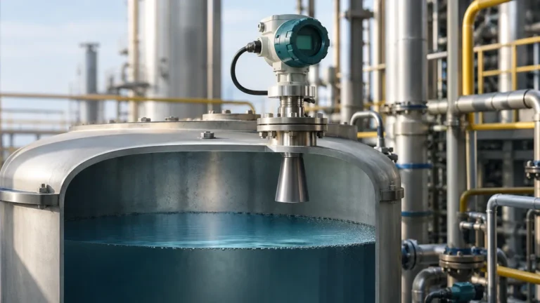
* Antenna Protrusion: For horn antennas, the bottom of the antenna should ideally extend at least 10 mm (0.4 inches) beyond the bottom of the nozzle into the tank. If the antenna is recessed deep within a narrow nozzle, the signal will reflect off the nozzle walls, creating a "ringing" effect that masks the true level.
* Nozzle Diameter vs. Length: If a long nozzle is unavoidable, a higher-frequency radar (like 80GHz) is recommended because its narrower beam can pass through the nozzle without touching the sides.
3. Avoiding Internal Obstructions
Radar waves travel in a cone shape. Any metallic object within this cone—such as ladders, heating coils, agitators, or structural beams—will create a parasitic echo.
* Beam Path Clearance: Ensure the signal path is clear of obstructions. If an obstruction is unavoidable, many modern Radar Level Meters offer "False Echo Suppression" or "Background Subtraction" software. During commissioning, the user can map out these fixed reflections so the transmitter ignores them.
* Agitators: If the tank has an agitator, the installation should be positioned where the radar beam hits the surface at a point where the blades are not constantly passing through the beam path, or use software filtering to average out the intermittent interference.
4. Orientation and Alignment
* Verticality: The transmitter must be mounted perpendicular to the product surface. Even a few degrees of tilt can significantly reduce the signal strength returned to the sensor, especially on liquid surfaces which act like a mirror.
* Polarization: Most radar signals are polarized. Rotating the housing (and thus the antenna) can sometimes help minimize reflections from nearby walls or obstructions. Consult the manufacturer’s manual for the specific polarization orientation of your model.
Application-Specific Considerations
Liquid Level Measurement
In liquid applications, surface turbulence and foam are the primary challenges.
* Turbulence: Heavy agitation can cause the signal to scatter. Using a stilling well (a perforated pipe) can provide a calm surface for the radar to measure, though this requires a specific type of radar calibration.
* Foam: Some types of foam absorb radar signals entirely, while others reflect them. If thick, dense foam is present, a low-frequency radar (e.g., 6GHz or 26GHz) or a Guided Wave Radar (GWR) may be more effective than high-frequency 80GHz units.
Solids and Powders
Measuring solids involves dealing with dust and the "angle of repose."
* Angle of Repose: Unlike liquids, solids form a cone when filled. The radar should be positioned to aim at a representative part of the slope, typically 1/3 of the radius from the wall.
* Aiming Flanges: For solids, adjustable aiming flanges (swivel mounts) are highly recommended. These allow the operator to tilt the radar to point directly at the product surface to maximize signal return.
* Dust: While radar penetrates dust much better than ultrasonic sensors, extreme dust can still attenuate the signal. High-frequency 80GHz radars with self-cleaning lens antennas are preferred here.
Technical Limitations and Risks
While radar is robust, it is not a "one-size-fits-all" solution. Engineers must be aware of the following limitations:
1. Vacuum and Pressure: While radar works in a vacuum (unlike ultrasonic), the mechanical seals and flange ratings of the instrument must match the vessel’s design pressure and temperature.
2. Minimum Dielectric Constant: If the medium has an εr below 1.4, non-contact radar may struggle to detect the surface. In these cases, Guided Wave Radar or the use of a stilling well is necessary to concentrate the signal.
3. Condensation: Heavy condensation on the antenna lens can cause signal attenuation. Choosing an antenna with a PTFE (Teflon) cover or a drip-off design helps shed moisture.
Commissioning and Maintenance
Once the physical installation is complete, the following steps ensure long-term reliability:
* Zero and Span Calibration: Define the 4mA (empty) and 20mA (full) points relative to the tank bottom and the reference plane of the sensor.
* Echo Mapping: Perform a "dry run" or an empty tank scan to map out internal obstructions. This is the most critical step in any radar level transmitter installation guide.
* Periodic Inspection: Check for material buildup on the antenna. While many radars can "see through" thin layers of buildup, heavy crusting in chemical or mining applications will eventually degrade performance.
Frequently Asked Questions (FAQ)
Q: Can I install a radar level transmitter on a plastic tank?
A: Yes. Since radar waves pass through non-conductive materials like plastic or fiberglass, you can even mount the sensor above a closed plastic tank to measure the level inside without a nozzle. However, this results in some signal loss.
Q: How does temperature affect radar measurement?
A: Unlike ultrasonic sensors, radar is generally unaffected by air temperature, pressure, or vapor layers. However, the instrument's electronics and seals have specific limits (typically up to 250°C or higher with specialized cooling fins).
Q: Is 80GHz always better than 26GHz?
A: Not necessarily. While 80GHz offers a narrower beam and better accuracy, 26GHz is often more robust in the presence of heavy foam or steam and is generally more cost-effective for simple, large-scale liquid storage.
Q: What is the "Dead Zone" (Blocking Distance)?
A: This is the area immediately below the antenna where the device cannot measure accurately. It is usually between 50 mm and 300 mm depending on the frequency and antenna type. Ensure your maximum fill level does not enter this zone.
Conclusion
Precise level measurement is a synergy of advanced hardware and meticulous installation. By following this radar level transmitter installation guide, industrial operators can minimize signal interference and maximize the lifespan of their instrumentation. Whether managing volatile chemicals in the oil and gas sector or monitoring silos in the food industry, the correct application of Radar Level Meters ensures that process data remains a reliable asset for automation and safety.
Download Radar Level Transmitter Installation Guide as a PDF