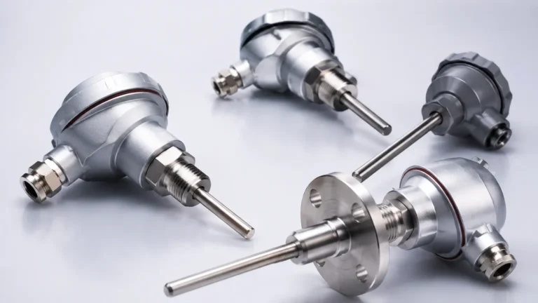
Rtd Sensor Accuracy
Rtd Sensor Accuracy
In industrial process control, the precision of temperature measurement is often the foundation upon which other critical data points, such as volume and level, are calculated. Resistance Temperature Detectors (RTDs) are widely regarded as the gold standard for accuracy and stability in these environments. Understanding rtd sensor accuracy is essential for engineers and technicians who must ensure that their systems operate within tight safety and efficiency margins. From chemical processing to water treatment, the choice of an RTD class and its proper installation can significantly impact the reliability of the entire measurement chain.
The Fundamental Principles of RTD Measurement
Before evaluating accuracy, it is necessary to understand the physical principles that govern how an RTD functions. An RTD operates on the principle that the electrical resistance of a metal increases as its temperature rises. This relationship is known as the temperature coefficient of resistance (TCR).
Most industrial RTDs utilize platinum as the sensing element due to its excellent corrosion resistance, wide temperature range, and highly linear resistance-to-temperature relationship. These are commonly referred to as Pt100 (100 ohms at 0°C) or Pt1000 (1000 ohms at 0°C) sensors. The standard relationship is defined by the Callendar-Van Dusen equation, which describes the resistance curve over a specified temperature range.
In the context of industrial automation, RTDs are frequently integrated into level measurement systems. For example, when using hydrostatic level transmitters or radar level meters, temperature data is required to compensate for changes in fluid density or to ensure the dielectric constant remains stable. For comprehensive instrumentation options, engineers often consult a Main Page for integrated level and temperature solutions.
Defining RTD Sensor Accuracy: Standards and Classes
RTD sensor accuracy is not a single fixed value but a range defined by international standards, most notably IEC 60751 and ASTM E1137. These standards categorize sensors into "Classes" based on their tolerance levels at specific temperatures.
IEC 60751 Accuracy Classes
The IEC 60751 standard is the most globally recognized framework for platinum RTDs. It defines four primary tolerance classes for thin-film and wire-wound sensors:
* Class AA (1/3 DIN): The highest standard for industrial applications, offering a tolerance of ±(0.1 + 0.0017 |t|) °C.
* Class A: High-precision sensors used in critical process control, with a tolerance of ±(0.15 + 0.002 |t|) °C.
* Class B: The standard industrial grade, suitable for most general-purpose applications, with a tolerance of ±(0.3 + 0.005 |t|) °C.
* Class C: Lower precision, often used in non-critical monitoring where cost is a primary factor, with a tolerance of ±(0.6 + 0.01 |t|) °C.
In these formulas, "|t|" represents the absolute value of the temperature in degrees Celsius. This indicates that the margin of error increases as the temperature moves further away from 0°C.
Practical Selection Table for RTD Accuracy
| Tolerance Class | Tolerance at 0°C | Tolerance at 100°C | Tolerance at 200°C | Application Suitability |
| :— | :— | :— | :— | :— |
| Class AA | ±0.10°C | ±0.27°C | ±0.44°C | Laboratory and high-precision chemical dosing |
| Class A | ±0.15°C | ±0.35°C | ±0.55°C | Pharmaceutical and food processing |
| Class B | ±0.30°C | ±0.80°C | ±1.30°C | General industrial tank level and HVAC |
| Class C | ±0.60°C | ±1.60°C | ±2.60°C | Basic ambient monitoring |
Factors Influencing Real-World Accuracy
While the class rating provides a theoretical baseline, several environmental and mechanical factors can degrade rtd sensor accuracy once the device is deployed in the field.
1. Lead Wire Resistance
An RTD is a resistance-based sensor, meaning the resistance of the wires connecting the sensor to the transmitter can be mistaken for temperature. This is a primary source of error in 2-wire configurations.
* 2-Wire RTDs: These provide no compensation for lead wire resistance. If a 100-ohm sensor has 1 ohm of lead wire resistance, the system will read approximately 2.5°C higher than the actual temperature. These are only recommended for very short distances or where high accuracy is not required.
* 3-Wire RTDs: The most common industrial configuration. It uses a third wire to measure the lead resistance and subtract it from the total. This assumes all three wires have identical resistance.
* 4-Wire RTDs: The most accurate configuration, typically used with Class AA sensors. It uses two wires to carry the excitation current and two independent wires to measure the voltage drop across the sensor, completely eliminating the effect of lead wire resistance.
2. Self-Heating
To measure resistance, a small current must be passed through the RTD. This current generates heat ($P = I^2R$). If the current is too high, the sensor will warm up, leading to a falsely high temperature reading. Most modern transmitters limit this current to less than 1 mA to minimize self-heating errors, but in stagnant air or low-conductivity fluids, this can still be a factor.
3. Insulation Resistance (IR) Leakage
At high temperatures, the insulation material within the sensor probe can begin to break down or absorb moisture. This creates a parallel resistance path, causing the measured resistance to drop and the indicated temperature to read lower than the actual value. High-quality manufacturing processes, such as those employed by Welk, involve hermetic sealing to prevent moisture ingress.
4. Immersion Depth and Stem Conduction
If an RTD is not immersed deeply enough into the process medium, heat can conduct along the sensor sheath to the cooler (or hotter) ambient environment outside the tank. This is known as stem conduction. A general rule of thumb for maintaining accuracy is an immersion depth of at least 10 times the diameter of the sensor protection tube.
Installation Considerations for Maintaining Accuracy
Proper installation is as critical as the sensor's inherent class rating. To maintain rtd sensor accuracy in industrial level measurement and process control, follow these guidelines:
1. Thermowell Selection: In high-pressure or corrosive environments, RTDs are housed in thermowells. While thermowells protect the sensor, they also slow down the response time. Ensure the use of a thermal conductive paste between the RTD tip and the thermowell bottom to minimize the air gap.
2. Vibration Mitigation: RTD elements, particularly thin-film types, can be sensitive to extreme vibration. In applications involving heavy pumps or mixers, use vibration-resistant RTD designs or ensure the probe is securely braced.
3. Shielding and Grounding: To prevent electromagnetic interference (EMI) from affecting the resistance signal, use shielded twisted-pair wiring. The shield should be grounded at only one end (usually the transmitter) to avoid ground loops.
4. Transmitter Matching: For the highest possible accuracy, the transmitter can be calibrated to the specific resistance curve of the individual RTD sensor (a process called sensor-transmitter matching or Callendar-Van Dusen calibration). This eliminates the "interchangeability error" inherent in standard class ratings.

Limitations of RTD Sensors
While RTDs offer superior accuracy compared to thermocouples or thermistors, they do have limitations:
* Temperature Range: RTDs are generally limited to a maximum of 600°C to 850°C, whereas thermocouples can reach much higher temperatures.
* Response Time: Due to their mass and the need for protective sheathing, RTDs typically respond slower to temperature changes than fine-wire thermocouples.
* Cost: The use of platinum makes RTDs more expensive than thermocouples, especially in high-accuracy classes or long probe lengths.
* Fragility: While industrial versions are ruggedized, the internal ceramic or glass components can be damaged by severe mechanical shock.
Frequently Asked Questions (FAQs)
What is the difference between Pt100 and Pt1000 accuracy?
Technically, the accuracy classes (Class A, B, etc.) apply to both. However, Pt1000 sensors are less affected by lead wire resistance in 2-wire setups because the lead resistance is a much smaller percentage of the total resistance. Pt100 is more common in industrial 3-wire and 4-wire systems due to its compatibility with legacy equipment.
How often should an RTD be calibrated to ensure accuracy?
In stable processes, annual calibration is standard. However, in applications with high vibration, thermal cycling, or corrosive environments, semi-annual checks are recommended. RTDs tend to "drift" over time, usually in a positive direction.
Can I use a Class A RTD with a 2-wire transmitter?
You can, but it is counterproductive. The error introduced by the lead wire resistance will likely exceed the tight tolerance of the Class A element, effectively turning it into a Class B or worse measurement.
How does temperature accuracy affect level measurement?
In hydrostatic level measurement, the sensor measures pressure, which is converted to level using the formula $P =
ho gh$ (Pressure = Density x Gravity x Height). Since density ($
ho$) changes with temperature, an inaccurate temperature reading leads to an incorrect level calculation. In large storage tanks, a 1°C error can result in significant volume measurement discrepancies.
Conclusion
Selecting the right RTD and understanding the variables that impact rtd sensor accuracy is vital for maintaining process integrity. By adhering to IEC 60751 standards, choosing appropriate wiring configurations, and following strict installation protocols, engineers can ensure highly reliable data. For those seeking professional-grade level measurement instruments that integrate these precision temperature technologies, visiting the Main Page provides access to a wide range of solutions tailored for industrial automation, water treatment, and chemical processing. Accurate measurement begins with understanding the physics of the sensor and ends with a commitment to quality instrumentation and installation.