Level 1 2 3 Switch
Level 1 2 3 Switch
In the landscape of industrial automation and process safety, the term "level 1 2 3 switch" refers to a multi-point detection strategy used to monitor and control the volume of liquids or solids within a vessel. Rather than providing a continuous stream of data, these systems utilize discrete Level Switches to trigger specific actions at three critical elevations. This tiered approach is fundamental for pump control, overflow prevention, and dry-run protection in sectors ranging from wastewater treatment to chemical processing.
Understanding the engineering behind these configurations requires a deep dive into the measurement principles, the logic of multi-point integration, and the selection criteria that ensure long-term reliability in harsh industrial environments.
Measurement Principles of Multi-Point Level Detection
To implement a level 1 2 3 switch system, engineers must first select the underlying sensing technology. Each technology interacts differently with the process media, and the choice depends on factors such as viscosity, pressure, and the presence of foam or turbulence.
Magnetic Float Technology
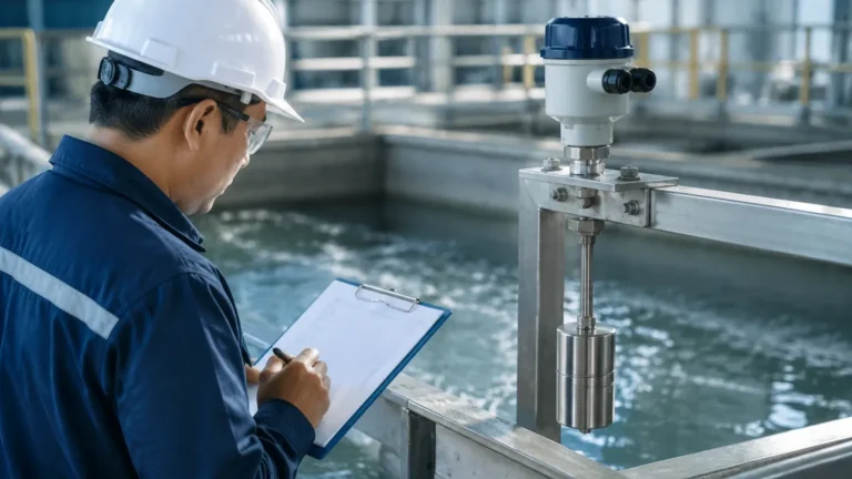
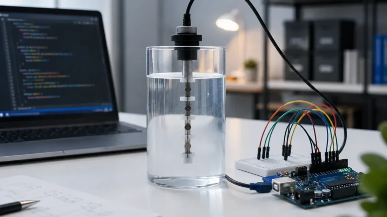
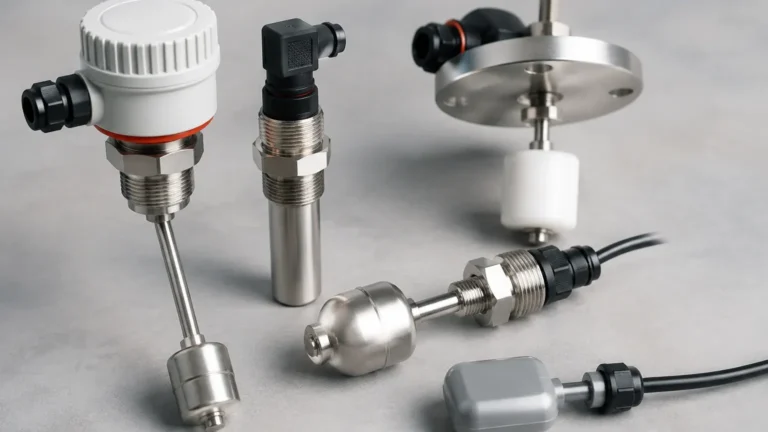
One of the most common methods for achieving three-point detection in a single instrument is the magnetic float level switch. This device consists of a hollow stem containing multiple reed switches at fixed intervals (Level 1, Level 2, and Level 3). A float containing a permanent magnet slides along the stem as the liquid level rises or falls. When the magnet aligns with a reed switch, the circuit closes or opens, sending a signal to the controller.
Vibrating Tuning Fork Technology
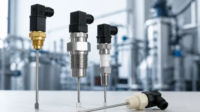
Vibrating level switches utilize a piezoelectric crystal to vibrate a fork at its natural frequency. When the fork is submerged in liquid or covered by solids, the frequency changes. This change is detected by the internal electronics and converted into a switching signal. While a single tuning fork usually provides one point of detection, a level 1 2 3 switch system can be constructed by installing three separate forks at different heights or using a specialized multi-point probe.
Ultrasonic Point Level Detection
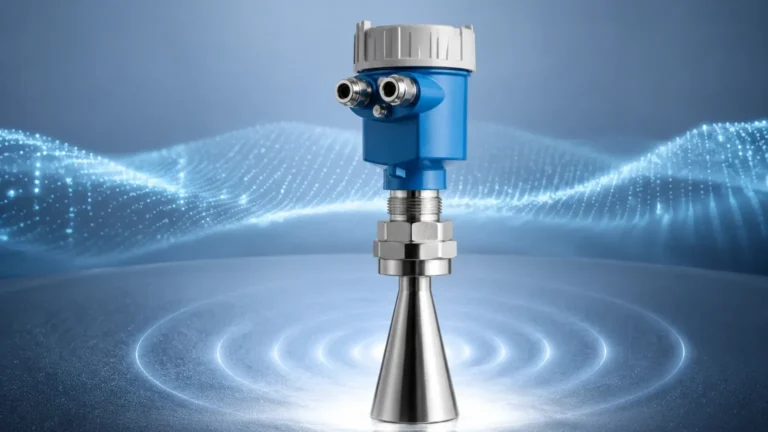
Ultrasonic switches use high-frequency sound waves. A sensor emits a pulse that reflects off the surface of the material. In point-level applications, the sensor detects the presence or absence of media at a specific gap. This is a non-contact method, making it ideal for corrosive or sticky substances that might foul a mechanical float.
Capacitance Level Detection
Capacitance switches measure the change in electrical capacitance between the sensor probe and the tank wall (or a reference probe). As the media covers the probe, the dielectric constant changes, triggering the switch. These are highly effective for both liquids and granular solids, provided the dielectric constant of the material is stable.
Defining the Roles: Level 1, Level 2, and Level 3
In a standard industrial configuration, the three levels are assigned specific logic roles within the Control System (PLC) or Distributed Control System (DCS).
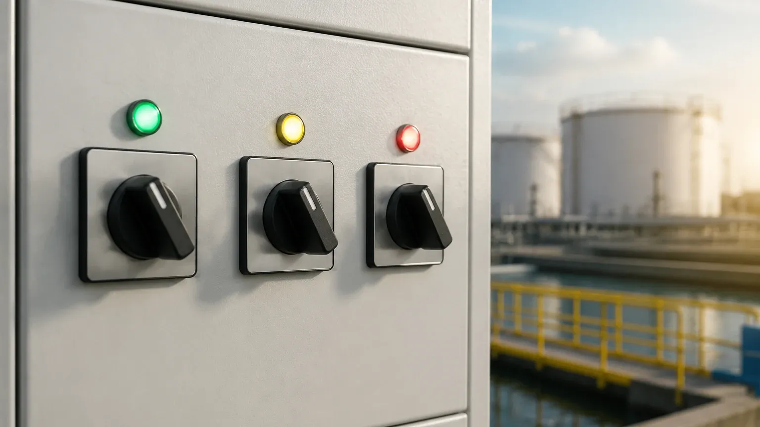
1. Level 1 (Low Level / Pump Start): This is typically the lowest point of detection. In a drainage application, Level 1 might trigger a pump to stop to prevent dry running. In a filling application, reaching Level 1 signals that the tank is nearly empty and needs replenishment.
2. Level 2 (High Level / Pump Stop): This is the intermediate point. It represents the "normal" maximum operating level. When the media reaches this point, the filling pump is usually deactivated, or a discharge pump is activated.
3. Level 3 (High-High Level / Emergency Alarm): This is the safety critical point. If the media reaches Level 3, it indicates that the Level 2 control has failed. This switch typically triggers an audible alarm and an emergency shutdown (ESD) of the inlet valves to prevent catastrophic overflow or environmental contamination.
Technical Selection Criteria
Selecting the right Level Switches for a 1-2-3 configuration requires evaluating the physical and chemical properties of the application. The following table provides a comparison of common technologies used in these setups.
| Feature | Magnetic Float | Tuning Fork | Ultrasonic (Point) | Capacitance |
| :— | :— | :— | :— | :— |
| Media Type | Clean Liquids | Liquids/Solids | Liquids/Slurries | Liquids/Granules |
| Viscosity Limit | Low to Medium | High (up to 10,000 cP) | Medium | Medium |
| Pressure Range | Up to 40 Bar | Up to 64 Bar | Up to 10 Bar | Up to 100 Bar |
| Temp. Range | -20°C to 150°C | -40°C to 150°C | -40°C to 80°C | -50°C to 200°C |
| Maintenance | Moderate (Moving parts) | Low | Low (Non-contact) | Moderate (Coating) |
| Cost | Economical | Mid-range | Higher | Mid-range |
Material Compatibility
The wetted parts of the switch must be compatible with the process media. For water and general industrial fluids, 304 or 316L stainless steel is standard. For highly corrosive acids, polymers like Polypropylene (PP), Polyvinylidene Fluoride (PVDF), or PTFE-coated stainless steel are required to prevent premature failure.
Output Options
Engineers must decide between different electrical outputs:
* Relay Outputs (SPDT/DPDT): Ideal for direct control of small motors or high-power alarms.
* Transistor Outputs (PNP/NPN): Best for high-speed switching and direct interfacing with PLCs.
* Two-wire (8/16mA): Often used in intrinsically safe circuits where the current change indicates the switch state.
Installation and Engineering Considerations
Proper installation is as critical as sensor selection. Even the most advanced level 1 2 3 switch system will fail if environmental factors are ignored.
Positioning and Turbulence
Switches should be installed away from the tank inlet to avoid false triggers caused by the force of incoming fluid. If the tank features an agitator or high turbulence, a stilling well (a vertical pipe that stabilizes the liquid level around the sensor) should be used. For float switches, ensure there is sufficient clearance for the float to move freely without hitting the tank wall or internal baffles.
Wiring and Cable Entry
In industrial environments, moisture ingress is a primary cause of switch failure. Installers must use proper cable glands and create a "drip loop" in the wiring to prevent condensation or rainwater from running down the cable into the housing. For hazardous areas, explosion-proof (Ex d) or intrinsically safe (Ex i) wiring standards must be strictly followed.
Mounting Orientation
* Top Mounting: Standard for multi-point float probes where the stem hangs vertically into the tank.
* Side Mounting: Common for tuning forks or single-point switches. In a 1-2-3 setup, three separate holes are drilled at different heights on the side of the vessel.
Limitations and Operational Constraints
While level switches are robust, they have inherent limitations:
* Buildup and Coating: In applications involving sticky resins or wastewater with high fat content, material can build up on the probe. Tuning forks are generally more resistant to this than floats, but heavy coating can eventually dampen the vibration and cause a false "covered" signal.
* Specific Gravity: Float switches rely on buoyancy. If the liquid's specific gravity (SG) is lower than the float's design (e.g., light oils with SG < 0.7), the float will not rise. Always verify the media density before selection.
* Dead Zones: Ultrasonic switches have a "blocking distance" (typically 50mm to 200mm) near the sensor face where measurements are not possible. This must be accounted for when setting the Level 3 (High-High) alarm point.
Frequently Asked Questions (FAQ)
Q: Can I use one instrument for a level 1 2 3 switch configuration?
A: Yes, multi-point magnetic float switches can incorporate three or more reed switches into a single probe, providing three distinct signals through one mounting flange. Alternatively, a continuous level transmitter (like radar) can be programmed with three software-based switching points.
Q: What is the difference between "Normally Open" (NO) and "Normally Closed" (NC) in this context?
A: This refers to the state of the switch when the media is not touching it. For safety-critical Level 3 (High-High) alarms, "Normally Closed" is often preferred because if a wire breaks, the circuit opens, triggering a fail-safe alarm.
Q: How often should these switches be tested?
A: In critical safety applications (SIL-rated systems), proof testing should be conducted annually. For standard process control, a semi-annual visual inspection and manual trigger test are recommended to ensure no mechanical binding or electrical degradation has occurred.
Q: Are level switches suitable for solids?
A: Yes, tuning forks and capacitance switches are excellent for powders and granules. However, float switches are strictly for liquids. For solids, the Level 3 switch must be positioned to account for the "angle of repose" (the cone shape the material forms as it fills).
By carefully aligning the technology with the specific requirements of the media and the vessel, a level 1 2 3 switch system provides a reliable, cost-effective, and essential layer of protection for modern industrial operations. For more detailed specifications on various sensing technologies, you can explore the range of Level Switches available for specialized industrial applications.