2 Position Lever Switch
2 Position Lever Switch
In the landscape of industrial automation and fluid management, the 2 position lever switch serves as a fundamental component for point level detection. While the term "lever switch" is often associated with simple electrical toggles, in the context of industrial level measurement, it refers to a robust mechanical or electro-mechanical device designed to trigger a discrete signal when a liquid reaches a specific height. These devices are essential for preventing tank overflows, protecting pumps from dry running, and managing automated filling cycles.
Selecting the right Level Switches requires an understanding of how mechanical motion translates into electrical logic. This guide examines the measurement principles, selection criteria, and practical installation requirements for 2 position lever-actuated level switches in B2B industrial environments.
Measurement Principles of Lever-Actuated Switches
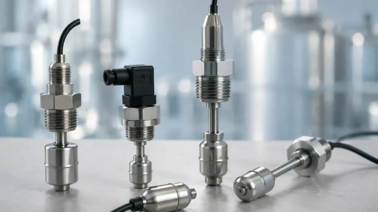
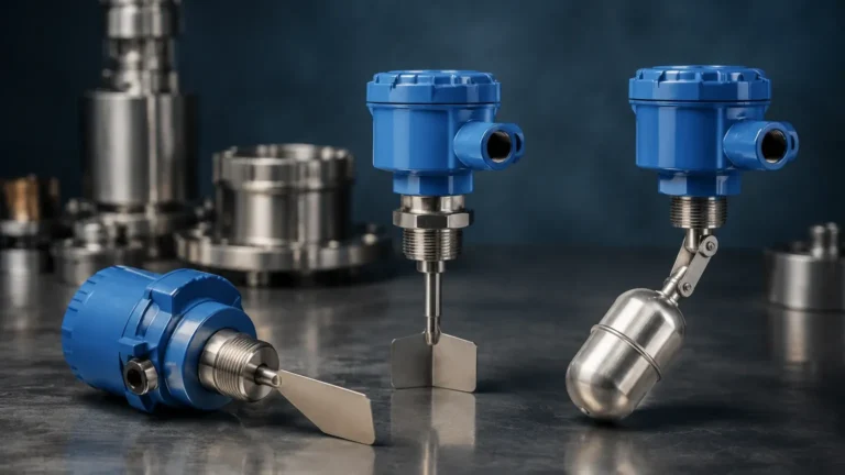
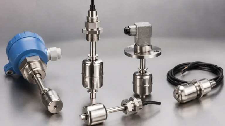
The operation of a 2 position lever switch in level measurement is primarily based on the principle of buoyancy and mechanical leverage. The system typically consists of three main elements: a float, a lever arm (or rod), and a switching mechanism.
The Buoyancy Effect
As the liquid level rises within a vessel, it exerts an upward force on a float. This float is attached to a lever arm that pivots at a fixed point. According to Archimedes' principle, the buoyant force is equal to the weight of the fluid displaced. When this force exceeds the weight of the float and the resistance of the internal spring or magnetic coupling, the lever moves.
Mechanical vs. Magnetic Coupling
There are two primary ways the motion of the lever is converted into an electrical signal:
1. Direct Mechanical Linkage: The lever arm passes through a flexible seal (such as a bellows or a diaphragm) and physically pushes a microswitch. This is common in low-pressure applications but can be a point of failure if the seal degrades.
2. Magnetic Coupling: This is the preferred method for high-pressure or hazardous environments. The lever arm moves a magnet inside a sealed pressure tube. Outside this tube, a second magnet or a reed switch senses the change in the magnetic field and toggles the circuit. This design ensures that the electrical components are completely isolated from the process media.
The "2 Position" Logic
The "2 position" designation refers to the binary output of the switch. In position one (the "normal" or "rest" state), the circuit is either open (NO) or closed (NC). When the liquid moves the lever to its limit, the switch snaps into position two (the "actuated" state). This clear transition is vital for PLC (Programmable Logic Controller) inputs, where a definitive On/Off signal is required to trigger alarms or control valves.
Key Components and Materials
To ensure longevity in harsh industrial environments, the construction materials of a 2 position lever switch must be compatible with the process fluid. Welk and other professional manufacturers typically offer a variety of configurations:
* The Float: Usually made from Stainless Steel (304 or 316L) for high pressure and temperature, or plastics like PP (Polypropylene) or PVDF for corrosive chemical applications. The density of the float must be significantly lower than the minimum density of the liquid being measured.
* The Lever Arm: The length of the lever arm determines the switching differential. A longer arm provides more torque, which is useful for high-viscosity liquids, but requires more physical space within the tank.
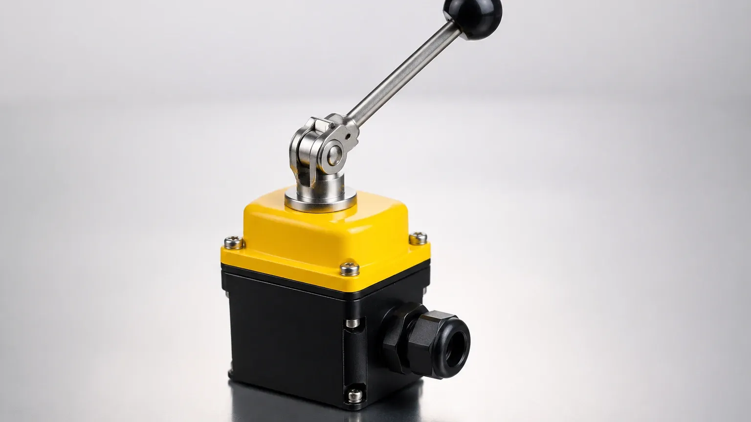
* Housing: The switch head housing contains the electrical terminals. For industrial use, these are often rated NEMA 4X or IP66/67 for weatherproofing, or explosion-proof (Ex d) for oil and gas applications.
Selection Criteria for Industrial Applications
Choosing a 2 position lever switch involves more than just matching a pipe size. Engineers must evaluate the physical and chemical properties of the application. The following table provides a baseline for evaluating lever-type switches against other common point-level technologies.
Table 1: Technology Comparison for Point Level Detection
| Feature | 2 Position Lever Switch | Tuning Fork (Vibrating) | Ultrasonic Switch |
| :— | :— | :— | :— |
| Measurement Principle | Mechanical Buoyancy | Frequency Damping | Sound Wave Reflection |
| Media Compatibility | Clean liquids, high temp | Most liquids and solids | Non-foaming liquids |
| Moving Parts | Yes (Lever/Float) | No (Vibration only) | No |
| Pressure Rating | Up to 40 bar (typ.) | Up to 64 bar | Low to Medium |
| Temperature Range | -40°C to +250°C | -50°C to +150°C | -20°C to +80°C |
| Maintenance | Periodic cleaning of float | Minimal | Low (Sensor face check) |
| Cost | Economical | Moderate | Higher |
Critical Specification Factors
1. Specific Gravity (SG): The liquid must have a specific gravity higher than the float's design limit. Most lever switches require an SG of at least 0.6 to 0.8.
2. Operating Pressure: In pressurized tanks, the float must be rated to withstand the external pressure without collapsing. Spherical stainless steel floats are typically rated for higher pressures than cylindrical ones.
3. Viscosity: Highly viscous liquids (above 1000 cP) can cause "drag" on the lever arm, slowing the response time or causing the float to stick. In these cases, a high-torque lever or a different technology like a tuning fork might be necessary.
4. Electrical Load: Ensure the switch contacts can handle the inrush current of the connected device. If the switch is directly controlling a pump motor, a secondary relay or motor starter is required to prevent contact welding.
Installation and Configuration Guide
Correct installation is the difference between a reliable safety system and a frequent source of false alarms. A 2 position lever switch can be mounted either horizontally (through the side of the tank) or vertically (from the top).
Horizontal Mounting
This is the most common orientation for lever switches. The switch is mounted via a flange or NPT/BSP thread on the side of the vessel.
* Orientation: Ensure the "Top" marking on the housing is facing upwards to allow the lever to move freely in the vertical plane.
* Clearance: There must be sufficient internal clearance for the lever arm to swing through its full arc without hitting tank walls or internal baffles.
Vertical Mounting
Vertical lever switches often use a "swing-arm" or a "displacer" design.
* Stilling Wells: If the liquid surface is turbulent due to an agitator or high-velocity inflow, the switch should be installed inside a stilling well (a vertical pipe with vent holes). This prevents the float from bouncing and causing "chatter" in the electrical signal.
Wiring and Logic
Most industrial level switches provide SPDT (Single Pole Double Throw) or DPDT (Double Pole Double Throw) contacts.
* Normally Open (NO): The circuit closes when the level rises.
* Normally Closed (NC): The circuit opens when the level rises (often used for high-level fail-safe logic).
Practical Selection Table for Common Media
| Media Type | Recommended Material | Lever Type | Consideration |
| :— | :— | :— | :— |
| Potable Water | 304 Stainless Steel | Standard Horizontal | Simple, low maintenance. |
| Sulfuric Acid | PVDF or PTFE Coated | Magnetic Coupled | Chemical resistance is priority. |
| Hydraulic Oil | 316 Stainless Steel | High-Pressure Float | Check for oil compatibility with seals. |
| Wastewater | 316 Stainless Steel | Large Diameter Float | Risk of debris buildup; use large float. |
| Diesel Fuel | Aluminum/Stainless | Explosion-proof Head | ATEX/IECEx certification required. |
Limitations and Operational Challenges
While the 2 position lever switch is a workhorse of the industry, it is not a "one-size-fits-all" solution. Engineers should be aware of the following limitations:
* Build-up and Scaling: In applications like lime slurry or wastewater, solids can accumulate on the lever pivot or the float. This increases the weight of the assembly, potentially causing it to sink or stick in one position. Regular inspection cycles are mandatory in these environments.
* Turbulence: Rapidly fluctuating levels can cause the switch to toggle rapidly. This can be mitigated by using a PLC timer (debounce) or a physical stilling well.
* Interface Measurement: Standard lever switches are designed for a single liquid. If you need to detect the interface between oil and water, the float must be weighted specifically to sink in oil but float on water, which requires precise engineering.
Maintenance and Troubleshooting
A well-maintained lever switch can last for decades. The primary maintenance task is the "bucket test" or manual actuation.
1. Manual Actuation: Most industrial switches have a small external lever or a way to manually move the internal mechanism to verify that the electrical circuit triggers correctly.
2. Seal Inspection: For non-magnetically coupled switches, check the bellows or diaphragm for cracks or brittleness.
3. Float Integrity: Shake the float; if you hear liquid inside, the float has a pinhole leak and must be replaced immediately.
Frequently Asked Questions (FAQ)
Q: Can a 2 position lever switch be used for continuous level measurement?
No. A lever switch is a point-level device, meaning it only detects if the liquid is above or below a specific point. For continuous measurement (e.g., 0-100% full), you would need a radar level meter or a hydrostatic pressure transmitter.
Q: What is the difference between a 2 position switch and a 3 position switch?
In level control, a 2 position switch has one set point (e.g., High). A 3 position lever switch (less common in buoyancy designs but available in some manual controls) would have a center "Off" position and two active positions (e.g., High and Low). Usually, for High and Low detection, two separate 2 position switches are used.
Q: How do I handle foam on the liquid surface?
Mechanical lever switches are generally excellent for foam applications because the float reacts to the density of the liquid, effectively "ignoring" the light foam on top. This gives them an advantage over ultrasonic sensors which may reflect off the top of the foam.
Q: What is the maximum temperature these switches can handle?
With high-temperature gaskets and all-stainless construction, some lever switches can operate in environments up to 250°C (482°F). However, the electrical housing must be kept cool, often through the use of an extended neck or cooling fins.
For engineers seeking reliable, cost-effective point level detection, the 2 position lever switch remains a top-tier choice. By matching the material properties to the process media and ensuring proper installation, these devices provide the critical safety and control logic required in modern industrial automation. To explore specific models and technical data sheets, you can Review product options and application support to find the configuration that best suits your facility's requirements.