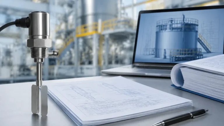
Level Switch Ball
Level Switch Ball
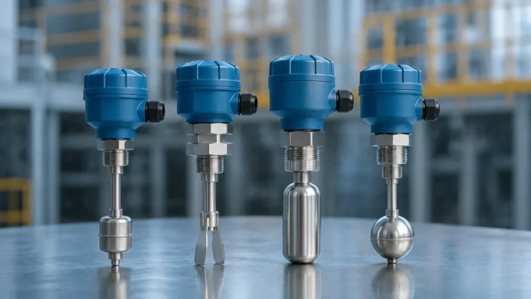
In the landscape of industrial automation, the level switch ball—commonly referred to as a float—remains one of the most reliable and widely utilized components for point-level detection. Despite the rise of non-contact technologies like radar and ultrasonic sensors, the mechanical simplicity and inherent reliability of a floating ball mechanism offer a cost-effective solution for many liquid handling applications. This guide explores the engineering principles, material considerations, and selection criteria for level switch balls in professional process environments.
Understanding the Measurement Principle of Level Switch Balls
The operation of a level switch ball is governed by Archimedes' principle of buoyancy. This principle states that any object, wholly or partially immersed in a fluid, is buoyed up by a force equal to the weight of the fluid displaced by the object. In the context of Level Switches, the "ball" is designed with a density lower than the liquid it is intended to measure, allowing it to move vertically along with the rising or falling liquid surface.
Mechanical vs. Magnetic Actuation
There are two primary ways a level switch ball communicates the liquid level to a control system:
1. Magnetic Coupling (Reed Switch): This is the most common design in modern industrial applications. The level switch ball contains an internal permanent magnet. As the ball slides up or down a stationary stem, the magnetic field passes through the stem wall (typically non-magnetic stainless steel or plastic) to actuate a hermetically sealed reed switch located inside. This design isolates the electrical components from the process media, significantly increasing the lifespan of the device.
2. Mechanical Linkage (Microswitch): In larger or older systems, the ball may be attached to a pivot arm or a cable. As the ball rises, the physical movement of the arm triggers a microswitch. This is often seen in heavy-duty sump pumps or large tank high-level alarms where high electrical current switching is required directly at the sensor.
Key Components and Construction
A functional level switch assembly consists of more than just the float. To ensure long-term accuracy, engineers must consider the synergy between the following components:
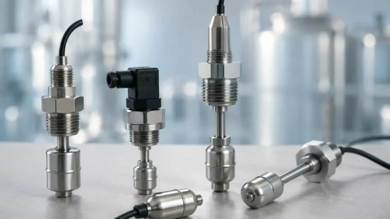
* The Float (Ball): The spherical or cylindrical element that provides buoyancy. Its volume and weight are precisely calibrated to ensure it floats in liquids of specific gravities.
* The Stem: The guide rod upon which the ball travels. It houses the wiring and the reed switches.
* Stop Collars: Small rings fixed to the stem that limit the travel of the ball, ensuring it stays within the range of the magnetic switch.
* The Housing/Junction Box: Located outside the tank, this protects the electrical terminations from environmental factors like moisture or dust.
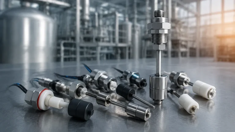
Material Selection for Level Switch Balls
Choosing the correct material for the level switch ball is the most critical step in the procurement process. The material must withstand the chemical nature of the fluid, the operating temperature, and the system pressure.
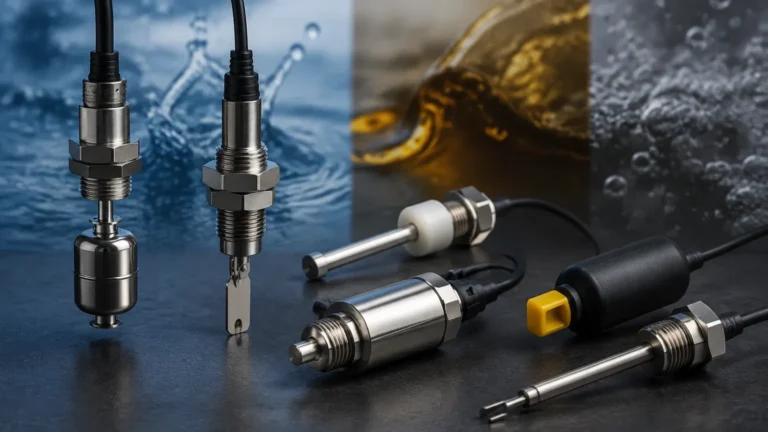
Stainless Steel (SS304/SS316L)
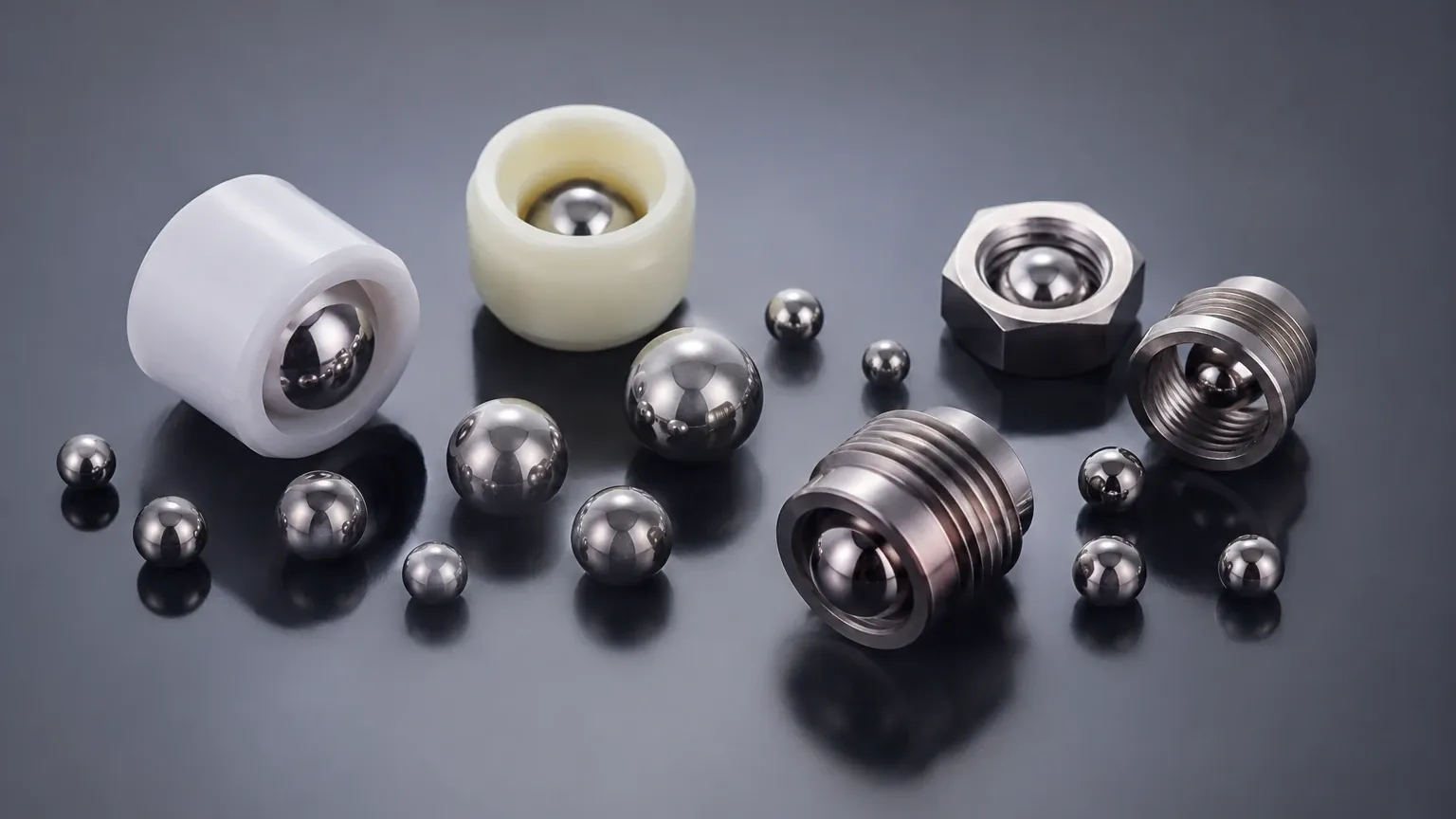
Stainless steel is the standard for high-pressure and high-temperature applications. SS316L is preferred in the chemical and food industries due to its superior corrosion resistance and hygienic properties. These balls are typically hollow and welded using precision plasma or laser techniques to maintain structural integrity under pressure.
Plastic (PP, PVC, PVDF)
Plastic level switch balls are ideal for highly corrosive acids, alkalis, and deionized water where metal contamination must be avoided.
* Polypropylene (PP): Suitable for general-purpose chemical resistance and temperatures up to 80°C.
* PVDF: Used for aggressive chemicals like bromine or high-purity applications, capable of handling higher temperatures than PP.
NBR (Nitrile Butadiene Rubber)
NBR floats are often used in oil, fuel, and hydraulic fluid applications. They are typically constructed as a solid, closed-cell foam, which makes them immune to punctures. If the surface is nicked, the ball will still float because the internal cells remain sealed.
Technical Specifications and Selection Table
When selecting a level switch ball, engineers must match the sensor's physical limits to the process conditions. The following table provides a general comparison of common configurations used in industrial automation.
| Material | Max Pressure (bar) | Max Temperature (°C) | Min. Liquid SG | Common Applications |
| :— | :— | :— | :— | :— |
| SS304/316 | 30 – 60 | -20 to 200 | 0.50 – 0.70 | Oil/Gas, Steam, Food Processing |
| Polypropylene | 5 – 10 | -10 to 80 | 0.60 – 0.85 | Water Treatment, Acid Tanks |
| NBR (Foam) | 10 – 20 | -20 to 100 | 0.45 – 0.65 | Diesel Fuel, Hydraulic Oil |
| PVDF | 10 – 15 | -10 to 120 | 0.75 – 0.90 | Etching Chemicals, Semiconductors |
*Note: 1 bar ≈ 14.5 PSI. Specific gravity (SG) of the liquid must always be higher than the minimum SG of the float to ensure buoyancy.*
Installation Guidelines and Best Practices
Proper installation is essential to prevent mechanical failure or false triggering of the level switch ball.
Orientation and Positioning
Level switches can be mounted vertically (from the top or bottom of a tank) or horizontally (through the side wall).
* Vertical Mounting: Allows for multiple switching points on a single stem. It is vital to ensure the stem is perfectly plumb so the ball can slide freely without friction.
* Horizontal Mounting: Usually limited to a single point (High or Low). These often use a hinged float design rather than a sliding ball.
Avoiding Turbulence
If the level switch ball is installed near a tank inlet or an agitator, the resulting turbulence can cause the ball to bounce, leading to "chatter" in the electrical signal. To mitigate this, engineers should use a stilling well—a pipe installed around the switch that allows the liquid level to rise and fall while shielding the ball from waves and splashes.
Clearance and Magnetic Interference
Ensure there is sufficient clearance between the ball and the tank wall to prevent sticking due to surface tension or debris. Additionally, if the tank is made of a ferromagnetic material (like carbon steel), the switch should be mounted far enough away to prevent the internal magnet from being attracted to the wall, which could cause the ball to hang up.
Limitations and Operational Risks
While highly effective, the level switch ball is not a universal solution. Understanding its limitations prevents costly downtime.
1. Viscosity and Coating: Highly viscous liquids (like heavy syrups or crude oil) can create drag on the ball, slowing its response or causing it to stick to the stem. Similarly, liquids that crystallize or leave a hard coating can seize the moving parts.
2. Particulate Matter: Large solids or fibrous materials in the liquid can become lodged between the ball and the stem, preventing movement. In wastewater applications, a regular cleaning schedule is required.
3. Mechanical Wear: Because it is a contact-based technology with moving parts, the ball and stem will eventually experience wear. In high-vibration environments, the reed switch inside the stem may also be susceptible to premature failure if not properly dampened.
4. Pressure Crushing: Hollow metal balls have a "collapse pressure." If the process pressure exceeds this limit, the ball will implode, lose its buoyancy, and sink to the bottom of the tank, resulting in a permanent "low level" signal.
Maintenance and Troubleshooting
A proactive maintenance strategy for level switch balls involves periodic physical inspections.
* Check for Buoyancy: Periodically remove the sensor and ensure the ball moves freely along the full length of the stem.
* Inspect for Pitting: In chemical applications, check the surface of the ball for signs of corrosion or pitting, which could lead to a breach in the hollow shell.
* Electrical Continuity: Use a multimeter to verify that the reed switch opens and closes at the correct positions on the stem. If a switch remains "stuck" closed regardless of the ball's position, the reed switch has likely fused due to an electrical surge and the unit must be replaced.
Frequently Asked Questions (FAQs)
Q: Can a level switch ball be used in hazardous (Ex) areas?
A: Yes, but the switch must be used in conjunction with an intrinsically safe (IS) barrier or be housed in an explosion-proof enclosure. Since the internal reed switch is a "simple apparatus," it is easily integrated into protected circuits.
Q: How do I choose between a spherical and a cylindrical ball?
A: Spherical balls generally offer better buoyancy for a given diameter and are better for high-pressure applications. Cylindrical balls are often used when the mounting hole (nozzle) is narrow, as they can have a smaller diameter while maintaining enough volume to float.
Q: What is the "Dead Zone" in level switch installation?
A: The dead zone is the area at the very top and bottom of the stem where the ball cannot travel or where the magnetic field cannot reach a switch. When designing a tank, ensure your critical alarm points are not located within these zones (typically the first and last 50mm of the stem).
Q: Can I use a stainless steel ball in a plastic tank?
A: Absolutely. The tank material does not affect the buoyancy of the ball. However, ensure the mounting hardware (flange or thread) is compatible with the tank's connection points.
For engineers requiring precise point-level control, the level switch ball remains a foundational tool. By carefully matching material properties to the chemical and physical environment of the process, these sensors provide years of maintenance-free service in even the most demanding industrial settings.