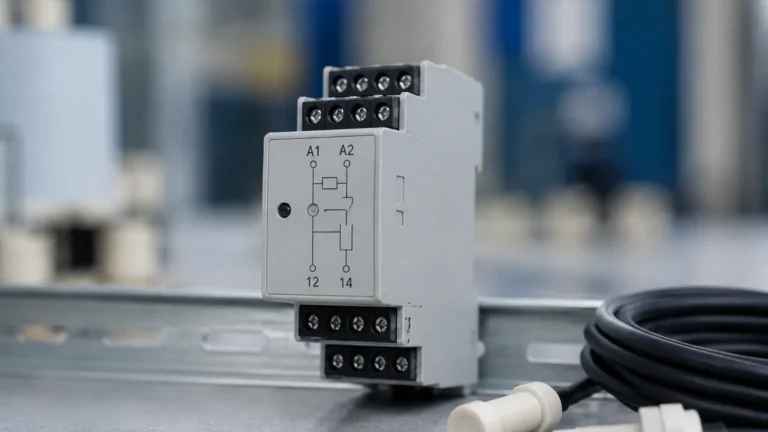
K Switch Limit Switch
K Switch Limit Switch
In the field of industrial automation and fluid management, the precise detection of position and level is fundamental to operational safety and process efficiency. Among the various components used to achieve this, the k switch limit switch stands out as a specialized electromechanical or electronic device designed to provide discrete feedback when a specific physical limit is reached. In the context of level measurement, these switches are often integrated into valve positioners, float-operated mechanisms, or bypass level indicators to signal high or low-level states.
Understanding the technical nuances of a k switch limit switch requires a deep dive into its mechanical construction, electrical characteristics, and its role within a broader instrumentation framework. As a professional manufacturer, Welk emphasizes the importance of selecting the right switching technology to ensure that industrial level measurement systems remain reliable under varying pressures, temperatures, and chemical exposures.
Measurement Principles and Operational Logic
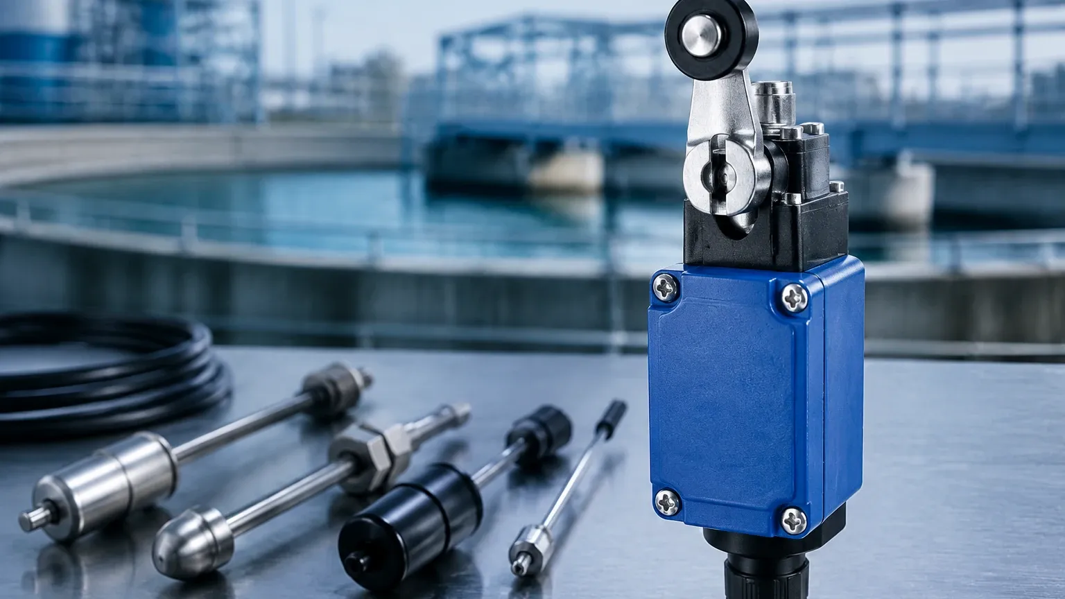
At its core, a limit switch is a device that converts mechanical motion into an electrical signal. For a k switch limit switch, this transition is typically triggered by the movement of a process component—such as a rising float or a rotating valve stem—making contact with the switch's actuator.
Mechanical Actuation
In mechanical versions, the actuator (which may be a lever, plunger, or roller) is physically moved by the process media or a linked mechanical arm. This movement shifts a set of internal contacts. The "K" designation often refers to a specific contact configuration or a series of switches known for their high repeatability and ruggedized housing, frequently utilized in valve position monitors that accompany Level Switches.
Proximity and Magnetic Sensing
In many modern level measurement applications, the "switch" logic is executed without physical contact between the media and the electrical components. For example, in a magnetic level gauge, a float containing a permanent magnet moves within a chamber. As the float passes a k switch limit switch mounted on the exterior, the magnetic field closes a reed switch or triggers a Hall-effect sensor. This non-contact principle is preferred in high-pressure or corrosive environments where maintaining a hermetic seal is critical.
Electrical Output Configurations
Most k switch limit switches offer one of the following contact arrangements:
- SPDT (Single Pole Double Throw): A common configuration providing one normally open (NO) and one normally closed (NC) contact.
- DPDT (Double Pole Double Throw): Provides two sets of SPDT contacts, allowing for the simultaneous switching of two independent circuits (e.g., a local alarm and a PLC input).
Technical Specifications and Selection Criteria
Selecting a k switch limit switch requires an evaluation of both the electrical load and the environmental conditions of the installation site. Engineers must look beyond simple "on/off" functionality to ensure long-term reliability.
1. Housing and Environmental Protection
Industrial environments often subject instrumentation to moisture, dust, and corrosive vapors. The housing of the switch should meet international standards, such as IP66 or IP67 for ingress protection. For hazardous locations, such as oil refineries or chemical processing plants, explosion-proof housings (NEMA 7, 9 or ATEX/IECEx certified) are mandatory to prevent internal sparks from igniting the external atmosphere.
2. Contact Ratings
The electrical capacity of the switch must match the load it is intended to drive. While many switches are used as low-current inputs for Programmable Logic Controllers (PLCs), others may need to directly switch motors or solenoids. Typical ratings might include 5A at 250V AC or 0.5A at 125V DC. Using a switch below its rated minimum load can lead to contact oxidation, while exceeding the maximum load will cause premature contact failure due to arcing.
3. Temperature and Pressure Limits
In level measurement, the switch often sits in close proximity to the process vessel. Standard switches may operate from -20°C to +80°C (-4°F to 176°F), but specialized high-temperature versions can withstand upwards of 200°C (392°F). If the switch is part of a submerged or high-pressure assembly, the structural integrity of the mounting interface (NPT or G threads) must be verified against the maximum process pressure.
Practical Selection Table
The following table provides a comparison of common technologies used in point-level detection and limit switching to help engineers identify the most suitable solution for their specific application.
| Feature | Mechanical Limit Switch | Magnetic Reed Switch | Inductive Proximity Switch | Ultrasonic Level Switch |
| :— | :— | :— | :— | :— |
| Detection Method | Physical Contact | Magnetic Field | Electromagnetic Field | Sound Wave Reflection |
| Common Use | Valve Position, Gates | Magnetic Level Gauges | Metallic Target Sensing | Liquid Level Detection |
| Durability | Moderate (Mechanical Wear) | High (No Contact) | Very High (Solid State) | High (No Moving Parts) |
| Max Temperature | Up to 150°C | Up to 250°C | Up to 100°C | Up to 80°C |
| Response Time | Fast (10-50ms) | Fast (1-5ms) | Very Fast (<1ms) | Moderate (100ms+) |
| Cost | Low | Moderate | Moderate | High |
Installation and Engineering Considerations
Proper installation is as critical as the selection of the k switch limit switch itself. Failure to follow engineering best practices can lead to false triggers or mechanical failure.
Mounting Orientation
Limit switches used in level applications must be mounted so that the actuator movement is perpendicular to the force applied by the process (e.g., the float arm). If the switch is mounted at an awkward angle, it may result in side-loading of the plunger or lever, leading to jammed mechanisms or bent components.
Wiring and Conduit Sealing
In outdoor or wash-down environments, water ingress through the conduit is a leading cause of switch failure. Installers should always use a drip loop in the wiring and ensure that conduit entries are properly sealed with industrial-grade cable glands. For switches used in hazardous areas, a poured conduit seal (sealing fitting) may be required within 450 mm (18 inches) of the switch housing to prevent the passage of gases.
Hysteresis and Deadband
In level control, hysteresis refers to the difference between the point where the switch activates and the point where it resets. A k switch limit switch with a defined deadband is useful in preventing "chatter"—the rapid cycling of the switch when the liquid surface is turbulent. If the process involves significant agitation, an external time-delay relay or PLC logic filter should be implemented to stabilize the signal.
Limitations and Operational Risks
While the k switch limit switch is a robust tool, it is not universal. Certain conditions can compromise its performance:
- Build-up and Scaling: In applications involving wastewater or viscous chemicals, material can accumulate on the actuator. This build-up may eventually prevent the switch from returning to its neutral position, resulting in a "stuck" signal.
- Mechanical Fatigue: Like all mechanical devices, the internal springs and contacts have a finite cycle life (often rated in millions of operations). In high-frequency applications, solid-state proximity switches may be a more durable alternative.
- Vibration: Heavy industrial machinery can produce vibrations that cause mechanical contacts to bounce. This can create electrical noise that confuses digital control systems. Using gold-plated contacts or hermetically sealed reed elements can mitigate some vibration-related issues.
Frequently Asked Questions (FAQ)
Q: Can a k switch limit switch be used for continuous level measurement?
A: No. Limit switches are discrete devices used for point-level detection (e.g., high, low, or intermediate levels). For continuous monitoring, technologies such as radar level meters or ultrasonic sensors are required.
Q: What is the difference between a limit switch and a level switch?
A: A level switch is a broad category of devices designed specifically to detect liquid or solid levels. A limit switch is a general-purpose position sensor. However, a k switch limit switch is frequently used *as* a level switch when it is triggered by a float or integrated into a level-indicating assembly.
Q: How do I test a k switch limit switch during maintenance?
A: With the power isolated, use a multimeter set to continuity or resistance mode. Manually actuate the switch and verify that the contacts transition from open to closed (or vice versa) according to the wiring diagram. For magnetic switches, move a test magnet past the sensing face to verify operation.
Q: Are these switches compatible with PLC inputs?
A: Yes, most are compatible. However, if using a mechanical switch with a low-voltage PLC input (e.g., 24V DC at a few milliamps), it is recommended to use switches with "bifurcated" or gold-plated contacts to ensure reliable electrical continuity despite low wetting current.
Conclusion
The k switch limit switch remains a staple of industrial process control due to its simplicity, reliability, and clear signal output. Whether used to confirm that a safety valve has closed or to signal that a storage tank has reached its maximum capacity, these devices provide the critical feedback loop necessary for automated systems. By understanding the mechanical principles, electrical requirements, and environmental constraints of the application, engineers can specify a switching solution that ensures long-term operational integrity. For those seeking comprehensive point-level solutions, exploring the full range of Level Switches is the first step toward a well-engineered measurement strategy.