Lower Gauges Meaning
Lower Gauges Meaning
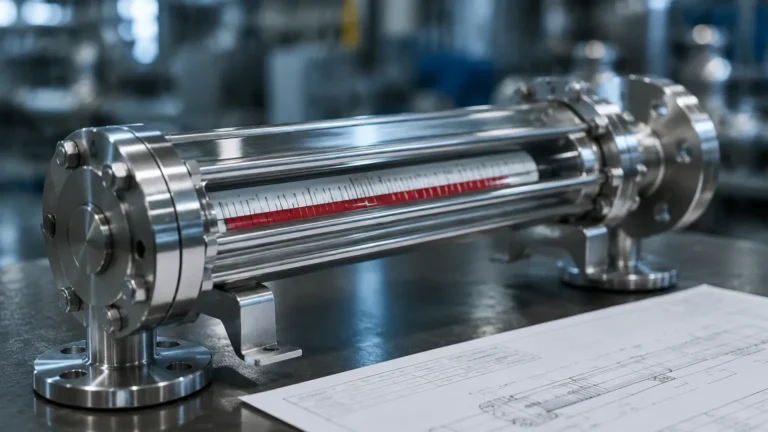
In the context of industrial process engineering and fluid management, the term "lower gauges" typically refers to level measurement instruments installed at the bottom or lower tapping points of a storage tank, pressure vessel, or bypass chamber. Understanding the lower gauges meaning is essential for plant operators and engineers who require precise visual verification of the "heel" or the lowest volume of liquid in a system. These instruments, primarily categorized under Magnetic & Local Level Gauges, provide a critical fail-safe for electronic sensors, ensuring that even during power outages or control system failures, the liquid level remains visible to personnel on the ground.
The Measurement Principle of Magnetic & Local Level Gauges
Before selecting a specific gauge based on its mounting position, it is vital to understand the underlying physics of local level measurement. Local gauges generally fall into two categories: visual glass gauges and magnetic level gauges (MLGs).
1. Magnetic Coupling Principle
Magnetic level gauges operate on the principle of buoyancy and magnetic coupling. A float containing a permanent magnet assembly is placed inside a non-magnetic bypass chamber (usually stainless steel). As the liquid level rises or falls, the float moves accordingly. Outside the chamber, a visual indicator—consisting of a series of bi-color magnetic flaps or a magnetic follower—is mounted. The magnetic field of the float penetrates the chamber wall, causing the flaps to rotate or the follower to move, providing a clear, high-visibility representation of the liquid level.
2. Hydrostatic and Communicating Vessels
Local gauges utilize the principle of communicating vessels. The liquid level in the bypass chamber or the gauge glass will always equalize with the level inside the main tank, provided the pressure and temperature remain consistent across both volumes. This allows for an accurate external representation of the internal process conditions.
Defining Lower Gauges Meaning in Industrial Applications
When engineers discuss the "lower gauges meaning," they are usually referring to one of three specific scenarios in a B2B industrial environment:
* Bottom-Mounted Indicators: In large-scale vertical tanks, a single gauge may not cover the entire height. A "lower gauge" is the instrument responsible for monitoring the bottom section of the tank, often starting from the zero-datum point up to a height of 1,000 mm or 2,000 mm.
* Pump Protection Monitoring: Lower gauges are specifically placed to monitor the minimum liquid level required to prevent pump cavitation. If the level drops below the lower gauge's visibility range, it indicates a critical state where the pump may draw in air or sediment.
* Multi-Section Gauge Arrays: For very tall vessels (exceeding 5 or 6 meters), multiple gauge sections are installed in an overlapping "staircase" or stacked configuration. The section at the very bottom is referred to as the lower gauge, while those above are the middle and upper gauges.
Technical Selection Criteria for Local Level Gauges
Selecting the correct instrument requires an analysis of the process media and the mechanical constraints of the vessel. Use the following table as a baseline for evaluating Magnetic & Local Level Gauges in your facility.
| Parameter | Magnetic Level Gauges | Reflex/Transparent Glass Gauges |
| :— | :— | :— |
| Max Pressure | Up to 320 bar (32 MPa) | Up to 250 bar (25 MPa) |
| Max Temperature | -196°C to +450°C | Up to +400°C |
| Visibility | Excellent (up to 30 meters away) | Moderate (requires proximity) |
| Safety | High (no glass, no leaks) | Moderate (risk of glass breakage) |
| Media Suitability | Corrosive, toxic, flammable | Clean, non-coating liquids |
| Maintenance | Low (occasional float cleaning) | High (glass cleaning/replacement) |
Installation Considerations for Lower-Mounted Gauges
Proper installation of lower gauges is paramount for accuracy and safety. Because these instruments are located at the bottom of the vessel, they are susceptible to sediment buildup and high hydrostatic pressure.
1. Nozzle Alignment: Ensure that the process connections (nozzles) on the tank are perfectly aligned with the gauge's inlets. Misalignment can cause mechanical stress on the bypass chamber, leading to leaks or float jamming.
2. Drain and Vent Valves: Every lower gauge must be equipped with a high-quality drain valve at the bottom and a vent valve at the top. This allows for the safe isolation and cleaning of the gauge without shutting down the entire process.
3. Specific Gravity (SG) Calibration: The float in a magnetic gauge is weighted specifically for the density of the liquid. If the "lower gauge" is measuring a heavy sludge or a multi-phase liquid (like water at the bottom of an oil tank), the float must be calibrated for the specific gravity of the bottom layer.
4. Support Brackets: For gauges exceeding 3 meters (approx. 10 feet) in length, intermediate support brackets are required to prevent vibration and structural fatigue, especially in outdoor environments subject to wind loads.
Limitations and Operational Risks
While local gauges are highly reliable, they are not without limitations. Engineers should be aware of the following risks when relying on lower-positioned instrumentation:
* Magnetic Interference: If the gauge is installed too close to large motors or high-voltage power lines, the magnetic field may interfere with the float's coupling to the indicator flaps.
* Coating and Scaling: In applications involving heavy oils or calcium-rich water, material can build up inside the chamber. This increases friction on the float, potentially causing it to stick. Regular flushing via the drain valve is necessary.
* Extreme Cold: In sub-zero environments, the liquid inside the gauge may freeze or become too viscous to move freely. In these cases, steam tracing or electric heat jackets are required to maintain fluidity.
The Role of Lower Gauges in Redundancy
In modern industrial automation, digital sensors like radar or ultrasonic transmitters provide data to the PLC (Programmable Logic Controller). However, the "lower gauges meaning" extends beyond simple measurement; it represents the final layer of visual verification. If a radar sensor fails due to foam or heavy vapor, the operator can physically walk to the tank and check the magnetic gauge to confirm the actual level. This redundancy is a core requirement for SIL (Safety Integrity Level) rated systems in chemical and petrochemical plants.
Frequently Asked Questions (FAQs)
Q: Can a lower gauge be used for interface measurement?
A: Yes. If you need to measure the interface between two liquids (e.g., oil and water), a magnetic level gauge can be equipped with a float weighted to sink in the upper liquid and float on the lower liquid. This is common for monitoring the water level at the bottom of fuel tanks.
Q: What materials are typically used for the bypass chamber?
A: For most industrial applications, 304 or 316L Stainless Steel is the standard. For highly corrosive environments involving acids, exotic materials like Hastelloy, Titanium, or PTFE-lined stainless steel are utilized.
Q: How do I know if my float is stuck?
A: If the tank level is known to be changing but the indicator remains static, the float may be stuck. This can often be diagnosed by passing a powerful external magnet along the chamber to see if the indicator flaps react. If they do, but the level still doesn't update, the float is likely trapped by debris.
Q: Is there a maximum height for a single-section lower gauge?
A: While some manufacturers can produce gauges up to 6 meters in a single piece, shipping and installation become difficult. Most engineers prefer to break the measurement range into 2-meter or 3-meter sections for easier handling and maintenance.
Conclusion
Understanding the lower gauges meaning is a prerequisite for designing safe and efficient tank farm operations. By selecting the appropriate Magnetic & Local Level Gauges and adhering to strict installation standards, industrial facilities can ensure continuous visibility of their most critical process levels. Whether used for pump protection, interface detection, or as a manual backup to automated systems, these instruments remain a cornerstone of modern process engineering.