A-1 Flow Equalization Basin
A-1 Flow Equalization Basin
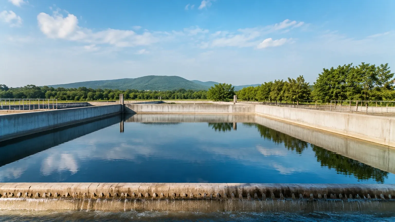
In industrial and municipal wastewater treatment, the management of influent flow variability is a critical engineering challenge. The A-1 flow equalization basin serves as the primary buffer stage, designed to dampen the fluctuations in flow rate and pollutant concentration that occur throughout a typical production cycle or diurnal period. By providing a consistent discharge rate to downstream processes—such as biological reactors, clarifiers, and filtration systems—the A-1 flow equalization basin prevents hydraulic overloading and ensures the stability of the treatment chemistry.
Effective operation of an a-1 flow equalization basin depends entirely on precise level monitoring. Because these basins are designed to fill during peak flow periods and empty during low flow periods, the level instrumentation must provide real-time data to control variable frequency drives (VFDs) on discharge pumps. Without accurate level measurement, the risk of basin overflow or pump cavitation increases significantly, potentially leading to environmental non-compliance or equipment failure.
Measurement Principles for Equalization Basins
Before selecting instrumentation for an a-1 flow equalization basin, it is essential to understand the physical principles governing the most common measurement technologies. In these applications, engineers typically choose between non-contacting methods (radar and ultrasonic) and contacting methods (hydrostatic pressure).
Radar Level Measurement (Time-of-Flight)
Radar level meters operate on the Time-of-Flight (ToF) principle. The sensor emits a high-frequency electromagnetic wave (typically in the 26 GHz or 80 GHz range) toward the liquid surface. The signal reflects off the surface and returns to the sensor. The distance is calculated using the formula:
$D = \frac{c \times t}{2}$
Where:
* D is the distance to the liquid.
* c is the speed of light.
* t is the measured transit time.
Radar is particularly effective in an a-1 flow equalization basin because it is unaffected by air temperature fluctuations, steam, or dust. High-frequency 80 GHz radar offers a narrow beam angle, which is advantageous if the basin contains internal structures like ladders or agitators.
Ultrasonic Level Measurement
Ultrasonic sensors also use the ToF principle but employ sound waves instead of electromagnetic waves. A transducer emits a pulse that bounces off the liquid surface. However, the speed of sound is heavily influenced by air temperature. While most modern ultrasonic sensors include integrated temperature compensation, extreme gradients can still introduce errors. In an a-1 flow equalization basin, ultrasonic sensors are often a cost-effective choice if the liquid surface is relatively calm and free of heavy foam.
Hydrostatic Level Measurement
Hydrostatic transmitters measure the pressure exerted by the liquid column above the sensor diaphragm. The relationship is defined by:
$P = \rho \times g \times h$
Where:
* P is the hydrostatic pressure.
* \rho is the density of the liquid.
* g is the acceleration due to gravity.
* h is the height of the liquid.
For an a-1 flow equalization basin, submersible pressure transducers are common. They are immune to surface foam and turbulence but require the liquid density to remain relatively constant for high accuracy.
Selection Criteria for the A-1 Flow Equalization Basin
Choosing the right instrument requires an evaluation of the specific characteristics of the influent. The a-1 flow equalization basin is often the first point of entry for raw effluent, meaning it may contain grease, solids, or corrosive chemicals.
1. Chemical Compatibility
The materials of construction for the sensor must withstand the pH levels and chemical constituents of the wastewater. For acidic or alkaline influent, PVDF or PTFE-coated sensors are preferred. For standard municipal applications, 316L stainless steel is often sufficient for submersible components.
2. Surface Conditions
If the a-1 flow equalization basin utilizes aeration to prevent septicity or to assist in mixing, the surface will likely be turbulent or covered in foam. Radar is generally superior in these conditions, as microwave signals can penetrate foam more effectively than ultrasonic sound waves.
3. Physical Dimensions
The depth of the basin dictates the required range of the sensor. Most industrial equalization basins range from 3 meters to 10 meters in depth. Radar and ultrasonic sensors must be selected with a "dead zone" (blocking distance) in mind, ensuring the basin can be filled to its maximum design level without the liquid entering the sensor’s blind spot.
Selection Comparison Table
| Feature | Radar (80 GHz) | Ultrasonic | Hydrostatic |
| :— | :— | :— | :— |
| Measurement Range | Up to 30m+ | Up to 15m | Up to 100m |
| Accuracy | ±1 mm to ±2 mm | ±0.25% of range | ±0.1% to ±0.5% |
| Foam Resistance | Excellent | Poor | Excellent |
| Steam/Vapor Impact | None | High | None |
| Maintenance | Low (Non-contact) | Low (Non-contact) | Moderate (Contact) |
| Cost | Higher | Moderate | Lower |
For a detailed overview of available hardware and technical specifications, engineers should Review product options and application support on the Welk Main Page.
Installation Considerations
Proper installation is as critical as sensor selection for the reliable operation of an a-1 flow equalization basin. Poor placement can lead to false echoes or erratic readings.
* Beam Clearance: For radar and ultrasonic sensors, the signal spreads in a cone. The path must be clear of pipes, brackets, or the basin wall. An 80 GHz radar typically has a beam angle of only 3° to 8°, allowing for installation in tighter spaces compared to 26 GHz models.
* Stilling Wells: In basins with high-velocity influent or heavy agitation, a stilling well (a vertical pipe) can be installed. This provides a calm surface for the sensor to measure, though it requires regular cleaning to prevent the buildup of solids or "ragging."
* Submersible Positioning: Hydrostatic sensors should be mounted away from the direct path of influent pipes to avoid dynamic pressure errors. They should be suspended approximately 100 mm to 300 mm above the basin floor to prevent silt or sludge from burying the diaphragm.
* Environmental Protection: Outdoor a-1 flow equalization basins subject ultrasonic sensors to direct sunlight. A sunshade is recommended to prevent the sensor body from heating up, which can skew the internal temperature compensation and lead to inaccurate distance calculations.
Limitations and Potential Risks
While modern instrumentation is robust, the environment of an a-1 flow equalization basin presents specific risks:
1. Build-up and Fouling: In industrial settings, fats, oils, and grease (FOG) can accumulate on the face of an ultrasonic transducer or the diaphragm of a hydrostatic sensor. This buildup can cause a "loss of echo" or a constant pressure offset. Non-contact radar is the most resistant to this issue.
2. Atmospheric Pressure Changes: For hydrostatic sensors, the cable must include a vent tube to compensate for changes in atmospheric pressure. If this tube becomes blocked or moisture enters it, the level reading will drift.
3. Signal Absorption: Extremely thick, heavy foam can occasionally absorb radar signals if the frequency is too low. In these rare cases, high-power 80 GHz units or guided wave radar (GWR) may be required.
Maintenance and Calibration Protocols
To ensure the longevity of the level control system in an a-1 flow equalization basin, a scheduled maintenance program is necessary.
* Visual Inspection: Monthly checks for physical buildup on the sensor face or mounting hardware.
* Verification: Quarterly verification of the electronic reading against a manual tape measure or a secondary reference point in the basin.
* Cleaning: For hydrostatic sensors, the diaphragm should be cleaned with a soft cloth and a compatible solvent if grease accumulation is noted. Never use sharp objects to clean a pressure diaphragm.
* Firmware Updates: For smart radar sensors, ensure the signal processing algorithms are updated to the latest version to improve false-echo suppression.
Frequently Asked Questions (FAQs)
Q: Can I use a float switch in an a-1 flow equalization basin?
A: While float switches can be used for high-level alarms, they are generally not suitable for continuous level control in equalization basins. They are prone to fouling from solids and do not provide the granular data needed for VFD pump control.
Q: How does the dielectric constant affect radar measurement in wastewater?
A: Wastewater is primarily water-based, which has a high dielectric constant (εr ≈ 80). This makes it an excellent reflector for radar signals, ensuring a strong return signal even in turbulent conditions.
Q: Is it necessary to use explosion-proof sensors?
A: This depends on the classification of the area. If the a-1 flow equalization basin collects runoff that might contain hydrocarbons or volatile organic compounds (VOCs), Intrinsic Safety (IS) or Explosion-Proof (Ex-d) ratings are typically required by local safety codes.
Q: What is the benefit of using a 4-20mA HART output?
A: HART (Highway Addressable Remote Transducer) allows for digital communication over the standard analog loop. This enables remote diagnostics and configuration, which is highly beneficial for sensors mounted in hard-to-reach areas of the basin.
By carefully considering the measurement principles and the specific environmental demands of the a-1 flow equalization basin, engineers can implement a level control strategy that optimizes plant performance and protects downstream assets. For further technical guidance on selecting the appropriate instrument for your specific process, visit the Welk Main Page.