Ametek Float
Ametek Float
In the landscape of industrial process control, float-based level measurement remains one of the most reliable and widely implemented technologies. Specifically, the engineering behind the Ametek float system—often associated with magnetostrictive level transmitters—represents a high-precision approach to determining liquid interfaces and total levels in storage tanks and process vessels. This guide examines the underlying physics, selection criteria, and practical application of float-based sensing to assist engineers in optimizing their level measurement infrastructure.
Principles of Float-Based Level Measurement
Float-based measurement relies on the fundamental principle of buoyancy, as defined by Archimedes. An object immersed in a fluid experiences an upward force equal to the weight of the fluid it displaces. In industrial level sensing, a float is engineered with a specific density that allows it to remain at the surface of a liquid (total level) or at the boundary between two immiscible liquids (interface level).
The Magnetostrictive Principle
While traditional float switches use mechanical movement to trigger a contact, advanced systems like the Ametek float utilize magnetostriction for continuous measurement. This process involves several key components:
1. The Waveguide: A wire made of magnetostrictive material (typically a ferromagnetic alloy) housed within a sensing probe.
2. The Float: A buoyant element containing a permanent magnet that slides along the probe as the liquid level changes.
3. The Electronics Head: A circuitry unit that sends a current pulse down the waveguide.
When the current pulse (the interrogation pulse) travels down the waveguide, it creates a circular magnetic field. When this field intersects with the magnetic field of the float, a torsional strain wave is generated at the point of intersection. This phenomenon is known as the Wiedemann effect. The strain wave travels back up the waveguide at a known speed (the speed of sound in the material). By measuring the time interval between the initial pulse and the return of the strain wave, the transmitter calculates the exact position of the float with sub-millimeter accuracy.
Magnetic Coupling in Level Gauges
Another common application for industrial floats is within magnetic level gauges. In this configuration, the float is contained within a bypass chamber or a stilling well. As the float rises and falls, its internal magnets couple with an external indicator or a transmitter mounted on the outside of the chamber. This provides a clear visual representation and a secondary electronic signal without the sensor coming into direct contact with the process media.
Component Materials and Design
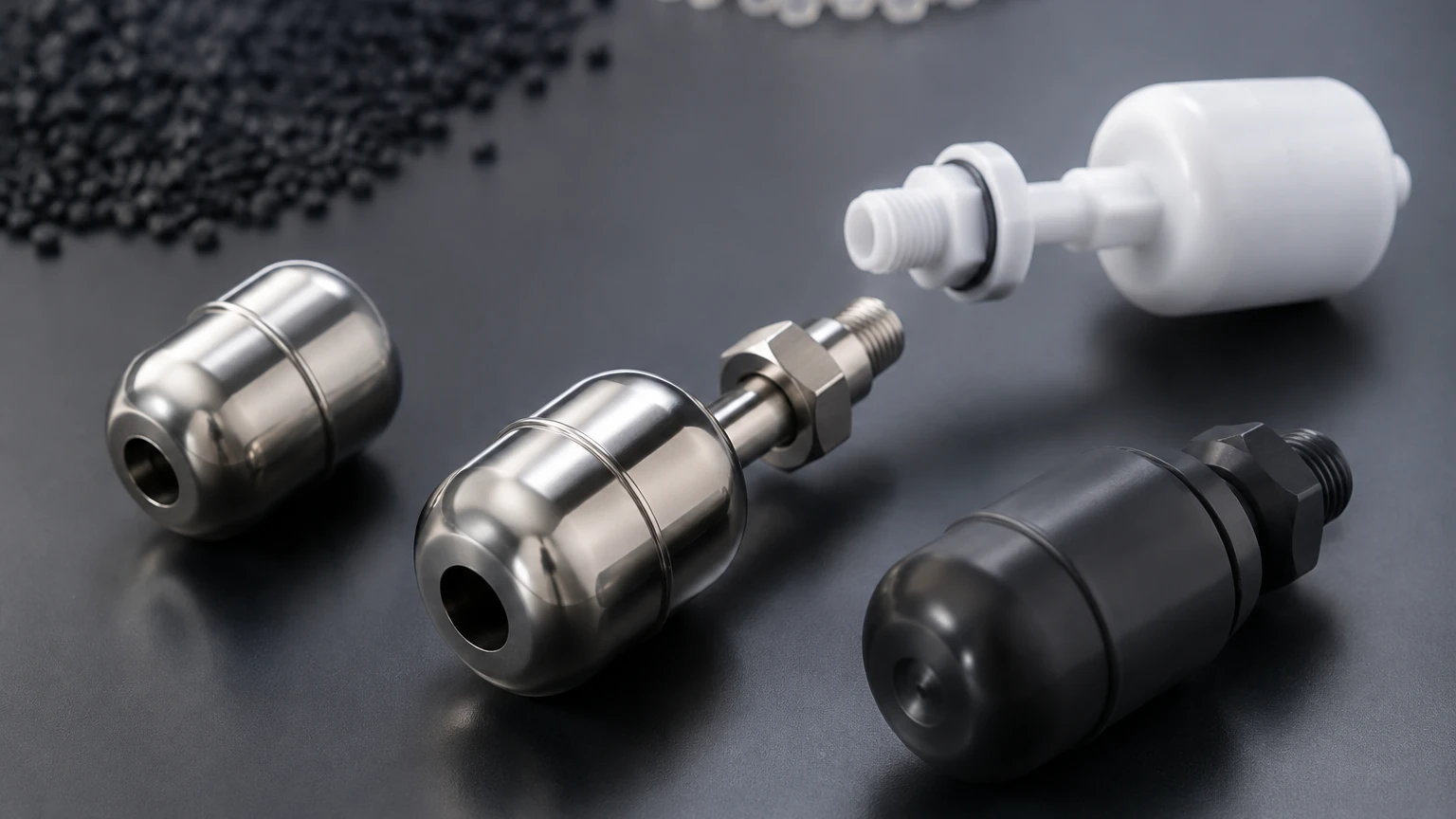
The durability of a float system is heavily dependent on material selection. Because the float is a wetted part, it must withstand the chemical properties, temperature, and pressure of the process fluid.
* 316L Stainless Steel: The standard material for most industrial applications due to its corrosion resistance and structural integrity.
* Titanium: Used for high-pressure or highly corrosive environments where stainless steel may fail.
* Hastelloy and Monel: Reserved for specialized chemical processes involving aggressive acids or chlorides.
* Plastics (PVC, PVDF, PP): Suitable for low-temperature, low-pressure corrosive applications where metallic floats are not feasible.
For professionals seeking high-performance level measurement hardware, the Main Page of Welk's product catalog offers a comprehensive range of industrial sensors designed to meet these rigorous material standards.
Selection Criteria and Engineering Specifications
Selecting the correct float requires a detailed analysis of the process conditions. A float that is too heavy will sink, while one that is too light may not provide the necessary stability in turbulent conditions. The following table outlines the primary evaluation criteria for industrial float systems.
| Parameter | Technical Requirement | Considerations |
| :— | :— | :— |
| Specific Gravity (SG) | Range: 0.40 to 1.50 | The float must be lighter than the liquid's SG to remain buoyant. |
| Operating Pressure | Up to 200 bar (2900 psi) | High pressure can collapse hollow floats; high-pressure designs are required. |
| Operating Temperature | -196°C to 450°C | Extreme temperatures affect the magnetic strength and material expansion. |
| Viscosity | Up to 1,500 cP | High viscosity can cause "drag" or sticking on the sensing probe. |
| Accuracy | ±0.01% of full scale | Magnetostrictive floats offer higher precision than standard reed-switch floats. |
| Interface Measurement | Min SG difference: 0.1 | Requires a float weighted to sink in the top layer and float on the bottom layer. |
Installation Considerations and Best Practices
Correct installation is critical to ensuring the longevity and accuracy of a float-based transmitter. Unlike non-contact radar, float systems are mechanical and require physical clearance.
Vertical Alignment
The sensing probe must be installed perfectly vertical. Even a slight tilt can increase friction between the float and the probe, leading to measurement lag or mechanical wear. In tall tanks (exceeding 4 meters or 13 feet), the probe should be secured at the bottom to prevent swaying caused by fluid movement.
Stilling Wells and Bypass Chambers
In tanks with internal agitation or high-velocity inflow, the float should be installed within a stilling well. A stilling well is a vertical pipe that protects the float from turbulence, providing a calm surface for measurement. Similarly, bypass chambers (side-mounted) allow for maintenance without emptying the primary vessel.
Magnetic Interference
Since magnetostrictive and magnetic level gauges rely on magnetic fields, they must be kept away from large motors, high-voltage power lines, or other equipment that generates significant electromagnetic interference (EMI). Standard industrial shielding is usually sufficient, but proximity to heavy machinery should be evaluated during the design phase.
Limitations and Environmental Factors
While highly accurate, float technology is not a universal solution. Engineers must be aware of the following limitations:
1. Coating and Buildup: In applications involving paraffin, bitumen, or crystallizing chemicals, material can build up on the probe or the float. This increases the float's weight and can eventually cause it to stick. Regular cleaning or the use of non-stick coatings (like PTFE) is necessary in these environments.
2. Mechanical Wear: Because the float moves physically along a rod, there is a long-term potential for wear. In high-cycle applications, the choice of bushing material within the float is critical.
3. Vessel Obstructions: Floats require a clear vertical path. Internal baffles, ladders, or heating coils must be mapped to ensure the float does not snag during operation.
4. Specific Gravity Shifts: If the process liquid's density changes significantly due to temperature fluctuations or composition changes, the float's immersion depth will change, introducing a small measurement error. For high-precision applications, temperature compensation should be integrated into the transmitter electronics.
Comparison with Non-Contact Technologies
In modern industrial automation, engineers often choose between float-based systems and non-contact technologies like radar or ultrasonic sensors.
* Float vs. Radar: Radar (specifically 80GHz FMCW) is excellent for extremely corrosive or agitated liquids where no contact is desired. However, float systems (magnetostrictive) often provide better performance in applications with heavy foam, which can absorb radar signals. Furthermore, floats are superior for interface measurement (e.g., oil-water separation) because they physically sit at the boundary, whereas radar may struggle to distinguish between layers with similar dielectric constants.
* Float vs. Ultrasonic: Ultrasonic sensors are cost-effective for open-air water applications but are limited by vacuum conditions, dust, and temperature gradients. Float systems are unaffected by the vapor space composition, making them more reliable in pressurized chemical tanks.
Frequently Asked Questions (FAQ)
Q: Can an Ametek float be used in high-pressure steam applications?
A: Yes, but it requires a high-pressure float design. Standard hollow floats may collapse under high pressure. Specialized high-pressure floats are often pressurized or made from high-strength alloys to maintain buoyancy without compromising structural integrity.
Q: How do I calibrate a magnetostrictive float transmitter?
A: Most modern transmitters are factory-calibrated. Field calibration typically involves setting the "Zero" (4mA) and "Span" (20mA) points using a handheld communicator or the onboard interface. Because the measurement is based on the speed of a strain wave, it does not drift like traditional analog sensors.
Q: What is the minimum specific gravity for a float?
A: Most industrial floats require a minimum specific gravity of approximately 0.45. For liquids with lower density, such as certain liquefied gases, specialized ultra-light floats or alternative technologies like guided wave radar are recommended.
Q: Is it possible to measure two different levels with one probe?
A: Yes. Using two floats with different weights—one designed to float on the upper liquid (total level) and one designed to sink through the upper liquid but float on the lower liquid (interface level)—a single magnetostrictive probe can provide two independent 4-20mA signals or digital outputs.
Q: How often should a float system be inspected?
A: In clean, non-corrosive service, an annual inspection is sufficient. In applications prone to scaling or buildup, quarterly inspections are recommended to ensure the float moves freely along the entire length of the probe.
By understanding these technical nuances, maintenance teams and system integrators can ensure that their level measurement systems provide the accuracy and reliability required for safe and efficient industrial operations.