Do Analyzer
Do Analyzer
In industrial process control and environmental monitoring, the dissolved oxygen (DO) analyzer is a critical instrument used to measure the amount of gaseous oxygen dissolved in a liquid. Whether in wastewater treatment, chemical manufacturing, or aquaculture, maintaining precise oxygen levels is essential for biological activity, product quality, and the prevention of equipment corrosion. As a professional manufacturer of industrial instrumentation, Welk provides comprehensive solutions that often integrate DO monitoring with critical level measurement to ensure holistic process automation.
Understanding Dissolved Oxygen Measurement Principles
Before selecting a do analyzer, it is vital to understand the underlying technologies used to detect oxygen molecules in a liquid medium. Most industrial DO analyzers rely on one of three primary sensing technologies: polarographic, galvanic, or optical (luminescent).
1. Polarographic Sensors (Clark Sensors)
Polarographic sensors consist of a cathode (usually gold) and an anode (usually silver) submerged in a potassium chloride (KCl) electrolyte solution, separated from the process medium by a gas-permeable membrane.
* Principle: An external voltage (polarizing voltage) is applied to the electrodes. Oxygen molecules diffuse through the membrane and are reduced at the cathode, creating an electrical current proportional to the partial pressure of oxygen.
* Considerations: These sensors require a "warm-up" period (typically 15–60 minutes) to stabilize the polarizing voltage before accurate readings can be taken. They also require a minimum flow rate of the liquid across the membrane because the sensor consumes oxygen during measurement.
2. Galvanic Sensors
Galvanic sensors operate similarly to a battery. They use two dissimilar metals (such as a lead anode and a silver or gold cathode) in an electrolyte solution.
* Principle: The difference in electrochemical potential between the two metals is sufficient to spontaneously reduce oxygen at the cathode without an external power source. The resulting current is proportional to the oxygen concentration.
* Considerations: Unlike polarographic sensors, galvanic sensors are ready for immediate use without a warm-up period. However, they also consume oxygen and require constant flow to prevent localized depletion at the membrane surface.
3. Optical (Luminescent) Sensors
Optical DO technology is the most modern approach and has gained significant traction in industrial applications due to its low maintenance requirements.
* Principle: The sensor tip contains a layer of oxygen-sensitive luminophore. A blue LED shines light on the luminophore, exciting it. As the luminophore returns to its ground state, it emits red light. Oxygen molecules "quench" this luminescence. The analyzer measures the phase shift or the decay time of the red light, which inversely correlates to the oxygen concentration.
* Considerations: Optical sensors do not consume oxygen, meaning they can measure in stagnant water. They are also immune to interference from gases like hydrogen sulfide ($H_2S$), which can poison electrochemical sensors.
DO Analyzer Selection Criteria
Choosing the correct do analyzer requires an evaluation of the process environment and the specific goals of the measurement. Engineers should consider the following factors:
1. Measurement Range and Accuracy: Most industrial applications require a range of 0–20 mg/L (ppm), but ultra-pure water applications (like boiler feed water) may require trace-level detection in the parts-per-billion (ppb) range.
2. Process Temperature and Pressure: Standard sensors usually operate between 0°C and 50°C (32°F to 122°F). High-pressure environments or sterilization processes (SIP/CIP) require specialized sensor housings and reinforced membranes.
3. Maintenance Frequency: Electrochemical sensors require periodic electrolyte replacement and membrane changes. Optical sensors only require the replacement of the sensor cap every 12 to 24 months.
4. Signal Output: Modern analyzers should support standard industrial protocols such as 4-20mA, RS485 (Modbus RTU), or HART to integrate with PLC and SCADA systems.
Practical Selection Table
| Feature | Polarographic | Galvanic | Optical (LDO) |
| :— | :— | :— | :— |
| Oxygen Consumption | Yes | Yes | No |
| Warm-up Time | 15–60 Minutes | None | None |
| Flow Dependency | High | High | None |
| Maintenance | High (Electrolyte/Membrane) | High (Electrolyte/Membrane) | Low (Sensor Cap) |
| Interference Risk | $H_2S$, $CO_2$, $Cl_2$ | $H_2S$, $CO_2$, $Cl_2$ | Very Low |
| Initial Cost | Moderate | Moderate | High |
| Long-term Cost | High | High | Low |
Integration with Level Measurement Systems
In many industrial setups, DO measurement is rarely an isolated requirement. For instance, in an aeration tank within a wastewater treatment plant, the do analyzer controls the blowers to maintain biological health, while level instruments ensure the tank does not overflow or run dry.
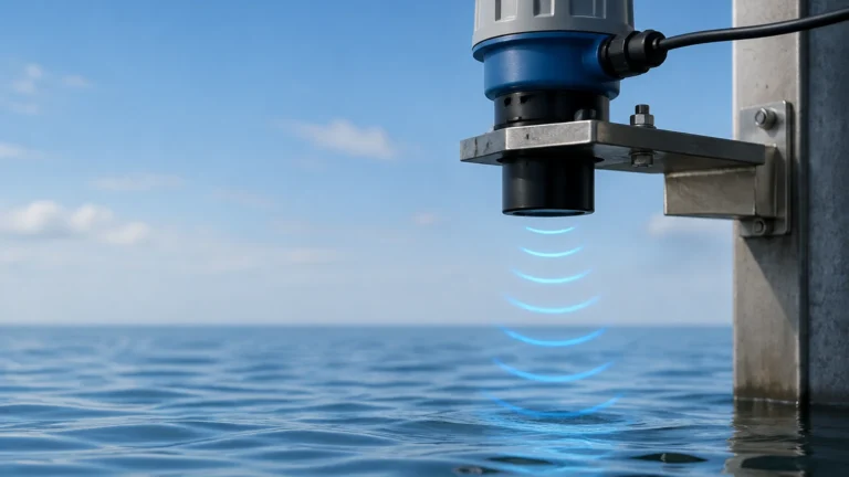
Welk specializes in the level measurement side of this equation. Accurate level data is crucial for calculating the total volume of liquid, which in turn helps determine the total mass of dissolved oxygen in a system. For comprehensive process control, engineers often visit the Main Page to select compatible radar level meters or ultrasonic sensors that work alongside DO analyzers. By combining high-accuracy level transmitters with reliable DO sensors, facilities can achieve better energy efficiency—only aerating the volume of water currently present in the tank.
Installation Best Practices
To ensure the longevity and accuracy of a do analyzer, proper installation is paramount. Follow these engineering guidelines:
* Avoid Bubble Accumulation: Do not install sensors directly above aeration diffusers. Rising bubbles can accumulate on the sensor membrane or optical window, leading to artificially high readings.
* Immersion Depth: The sensor should be submerged at least 300 mm (approx. 12 inches) below the surface to avoid atmospheric oxygen interference and surface turbulence.
* Mounting Angle: For electrochemical sensors, mount at an angle (usually 15° to 45° from vertical) to prevent air bubbles from being trapped against the membrane.
* Flow Velocity: If using a membrane-based sensor, ensure a minimum flow velocity of 0.3 m/s (1 ft/s). If the process is stagnant, a submersible stirrer may be required.
* Cable Routing: Keep sensor cables away from high-voltage power lines and frequency inverters to prevent electromagnetic interference (EMI) from degrading the low-voltage signal from the probe.
Limitations and Common Interference
While DO analyzers are robust, they are not immune to environmental challenges:
* Salinity: Dissolved salts reduce the solubility of oxygen. Most modern analyzers include a salinity compensation feature where the user enters the salinity value (in ppt or mS/cm) to correct the reading.
* Atmospheric Pressure: Oxygen partial pressure changes with altitude. Calibration should ideally occur at the same barometric pressure as the measurement site, or the analyzer must have an internal pressure sensor for automatic compensation.
* Fouling: In biological processes, biofilm or algae can grow on the sensor surface. This "fouling" creates a barrier that slows response time. Integrated cleaning systems, such as compressed air blasts or water jets, are recommended for high-fouling environments.
Maintenance and Calibration Procedures
Regular calibration is the only way to guarantee the accuracy of a do analyzer. There are two common methods:
1. Air Calibration (Water-Saturated Air): The sensor is held in a damp environment (like a calibration bottle with a wet sponge) at a known temperature. Since the percentage of oxygen in the air is constant (20.95%), the analyzer can set its slope based on the current barometric pressure.
2. Winkler Titration: This is a laboratory chemical method used to verify the analyzer's reading against a known liquid sample. While highly accurate, it is labor-intensive and usually reserved for periodic validation rather than routine calibration.
For electrochemical sensors, the electrolyte should be replaced if the sensor becomes sluggish or if the membrane shows signs of wrinkling or tearing. Optical sensors require a simple cap replacement when the internal luminophore reaches its expiration date.
Frequently Asked Questions (FAQs)
Q: How often should I calibrate my DO analyzer?
A: For most industrial applications, a weekly check is recommended. If the process is stable and the sensor is an optical type, this interval can often be extended to monthly. High-fouling environments may require daily checks until a cleaning schedule is established.
Q: Can a DO analyzer measure oxygen in non-aqueous liquids?
A: It depends on the sensor. Some electrochemical sensors can measure oxygen in oils or solvents, provided the membrane material is compatible with the chemicals. Optical sensors are generally limited to aqueous solutions because many solvents can dissolve the luminophore coating.
Q: What is the difference between mg/L and % saturation?
A: mg/L (or ppm) measures the actual concentration of oxygen molecules in the liquid. % Saturation measures the partial pressure of oxygen relative to the maximum amount the liquid can hold at that specific temperature and pressure. A DO analyzer can usually toggle between these units.
Q: Why does my DO reading change when the temperature changes, even if the oxygen level is constant?
A: Oxygen solubility is highly temperature-dependent. Cold water can hold significantly more dissolved oxygen than warm water. A do analyzer uses an internal thermistor to compensate for these solubility changes and provide a normalized reading.
By integrating a high-quality do analyzer with professional-grade level measurement tools from Welk, industrial operators can maintain optimal process conditions, reduce energy waste, and ensure regulatory compliance in water quality and chemical processing.