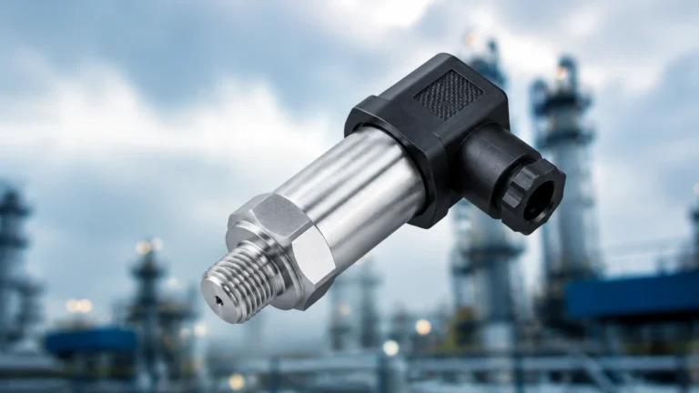
API 2350 5th Edition Key Changes Overfill Prevention
API 2350 5th Edition Key Changes Overfill Prevention
In the realm of industrial liquid storage, particularly within the petroleum, chemical, and oil and gas sectors, overfill prevention is not merely a safety protocol—it is a critical operational requirement. The American Petroleum Institute (API) Standard 2350 provides the industry-standard framework for preventing atmospheric storage tank overfills. With the transition to the 5th edition, the standard has shifted from a purely prescriptive set of rules to a more comprehensive, risk-based management system. Understanding the api 2350 5th edition key changes overfill prevention is essential for engineers and plant managers tasked with selecting and maintaining level measurement instrumentation.
The 5th edition emphasizes the integration of hardware, software, and human procedures into a cohesive Overfill Prevention Process (OPP). This article explores the technical nuances of these changes and provides guidance on selecting the appropriate level measurement technologies to ensure compliance and safety.
The Shift to a Risk-Based Management System
One of the most significant changes in the 5th edition of API 2350 is the requirement for a formal Overfill Prevention Management System (OPMS). Unlike previous versions that focused heavily on equipment specifications, the 5th edition mandates that facilities treat overfill prevention as a continuous process.
Key Components of the OPMS
1. Risk Assessment: Facilities must conduct a formal risk assessment for each tank to determine the appropriate category of overfill prevention. This assessment considers the potential consequences of an overfill, including environmental impact, fire hazards, and personnel safety.
2. Written Procedures: Operational procedures must be documented, covering everything from normal filling operations to emergency response and maintenance schedules.
3. Training and Competency: Personnel involved in tank operations must be trained and their competency verified regularly.
4. Equipment Maintenance: A rigorous schedule for proof testing and calibrating level sensors and alarms is required to ensure the system's reliability over time.
By moving toward a management system approach, API 2350 aligns more closely with functional safety standards like IEC 61511, emphasizing that hardware is only one part of a reliable safety loop.
Understanding Tank Categories and Hardware Requirements
API 2350 5th edition classifies tanks into three categories based on the level of automation and the role of the operator in preventing an overfill. Selecting the right level measurement technology depends heavily on which category a tank falls into.
Category 1: Manual Operations
Category 1 tanks rely entirely on the operator to monitor levels and terminate the receipt of product. These tanks require a local level indicator and a high-level alarm, but no automatic shut-off is present. The operator must be present throughout the entire filling process.
Category 2: Semi-Automated Systems
In Category 2, the tank is equipped with an independent high-high level alarm (HHLA) that transmits to a constantly attended location (such as a control room). While the system alerts the operator to a potential overfill, the termination of the liquid flow still requires manual intervention. The level sensor used for the alarm must be independent of the sensor used for continuous level gauging.
Category 3: Fully Automated Systems
Category 3 tanks represent the highest level of protection. These systems include an independent high-high level alarm and an automatic overfill prevention system (AOPS) that can terminate the flow without operator intervention. This is often implemented as a Safety Instrumented System (SIS). For Category 3, the level detection technology must be highly reliable and often redundant.
Measurement Principles for Overfill Prevention
To comply with API 2350, engineers must understand the underlying physics of the measurement technologies employed. The goal is to ensure that the sensor can accurately detect the liquid level even under adverse conditions, such as turbulence or vapor presence.
Radar Level Measurement (ToF)
Radar level meters, including both non-contact (pulse or FMCW) and guided wave radar (GWR), operate on the Time-of-Flight (ToF) principle. The sensor emits an electromagnetic signal that travels to the liquid surface and reflects back. By measuring the time taken for the signal to return, the device calculates the distance to the product.
* Non-contact Radar: Ideal for corrosive or volatile liquids as the sensor does not touch the medium. It is highly accurate and unaffected by changes in pressure or temperature.
* Guided Wave Radar: Uses a probe to guide the signal. This is particularly effective in tanks with low dielectric constants or where heavy foam is present, as the probe ensures a stronger return signal.
Ultrasonic Level Sensors
Ultrasonic sensors also use ToF but utilize sound waves instead of electromagnetic waves. While cost-effective for water treatment and some chemical applications, they are sensitive to air temperature fluctuations and heavy vapors, which can change the speed of sound and lead to inaccuracies. In API 2350 applications, they are typically reserved for stable, non-volatile liquids.
Point Level Switches (Vibrating Fork)
For high-high level alarms, vibrating fork switches are a common choice. The fork vibrates at its natural frequency in the air. When submerged in liquid, the frequency changes, triggering an electronic output. These are highly reliable "last line of defense" sensors because they are not affected by the physical properties of the liquid, such as density or conductivity.
Technical Selection Criteria for API 2350 Compliance
When evaluating instrumentation for an overfill prevention project, several factors must be weighed. The following table provides a comparison of common technologies used in Category 2 and Category 3 tanks.
| Technology | Category Suitability | Strengths | Limitations |
| :— | :— | :— | :— |
| Non-contact Radar | Cat 2 & 3 (Gauging/Alarm) | High accuracy, no moving parts, handles vapors well. | Higher initial cost; requires clear line of sight. |
| Guided Wave Radar | Cat 2 & 3 (Gauging/Alarm) | Excellent in foam, low dielectric liquids. | Probe can be subject to coating or mechanical stress. |
| Vibrating Fork Switch | Cat 2 & 3 (Independent Alarm) | Extremely reliable, simple to test, independent of gauging. | Point level only; no continuous data. |
| Hydrostatic Pressure | Cat 1 & 2 (Gauging) | Simple installation, reliable for constant density. | Affected by changes in liquid density/temperature. |
| Magnetic Level Gauge | Cat 1 & 2 (Local Indicator) | Clear visual indication, no power required for local view. | Mechanical parts can stick; high maintenance in dirty fluids. |
For comprehensive technical specifications and product ranges, engineers can Review product options and application support to find solutions that meet the specific requirements of their facility's risk assessment.
Key Changes in Alarm Levels and Response Times
The 5th edition provides clearer definitions for tank levels, which are critical for calculating the "Response Time" available to an operator or an automated system.
1. Critical High (CH): The level at which the tank overflows or is damaged (e.g., damage to a floating roof).
2. High-High (HH) Alarm: The trigger point for the overfill prevention system. The distance between HH and CH must be sufficient to allow for the total response time of the system.
3. High (H) Alarm: A pre-alarm used to notify the operator that the tank is reaching its working limit.
4. Maximum Working Level (MWL): The highest level used during normal operations.
Response Time Calculation:
One of the api 2350 5th edition key changes overfill prevention is the emphasis on calculating the required response time. This includes the time for the sensor to detect the level, the time for the alarm to reach the controller, and—most importantly—the time required for valves to close or pumps to stop. In a Category 2 tank, this must also include the time for an operator to acknowledge the alarm and take manual action.

Installation Considerations for Reliable Detection
Even the most advanced radar level meter will fail if installed incorrectly. To meet the safety requirements of API 2350, consider the following:
* Redundancy and Diversity: For Category 3 tanks, it is often recommended to use different technologies for the continuous gauging system and the independent high-high alarm (e.g., radar for gauging and a vibrating fork for the alarm). This prevents common-cause failures.
* Nozzle Positioning: Sensors should be mounted away from inlet pipes to avoid turbulence and false echoes. For radar, the nozzle height and diameter must be within the manufacturer's specifications to prevent signal interference.
* Stilling Wells: In tanks with significant internal obstructions or heavy turbulence, installing the level sensor inside a stilling well (a vertical pipe) can provide a stable surface for measurement. However, the well must be properly vented and free of debris.
* Environmental Protection: Ensure that all outdoor instrumentation is rated for the local climate, including sunshields for electronics and heating elements for applications where liquids might freeze or crystallize.
Limitations and Common Risks
While the 5th edition of API 2350 significantly improves safety, there are inherent limitations to consider:
* The Human Element: In Category 1 and 2 tanks, the system is only as reliable as the operator. Fatigue, distractions, or lack of training remain the primary risks in these categories.
* Proof Testing Gaps: A sensor that works today may fail tomorrow. API 2350 requires periodic proof testing. If the testing interval is too long, a "latent failure" (a failure that isn't apparent until the device is needed) could occur.
* Medium Changes: If a tank is repurposed for a different liquid, the existing level measurement technology must be re-evaluated. For example, a change in dielectric constant can affect radar performance, while a change in density will affect hydrostatic transmitters.
Frequently Asked Questions (FAQs)
Q: Does API 2350 5th Edition apply to all tanks?
A: It specifically applies to large atmospheric storage tanks (typically over 10,000 gallons or 38 cubic meters) storing Class I and Class II petroleum liquids. However, its principles are often applied as best practices for other industrial liquids.
Q: What is the difference between an "independent" alarm and a "redundant" one?
A: Independence means the alarm system (sensor, logic solver, and final element) does not share any components with the basic process control system used for daily gauging. Redundancy means having multiple components performing the same function to ensure that if one fails, the other takes over.
Q: How often should I proof test my overfill prevention sensors?
A: The frequency is determined by your facility's risk assessment and the manufacturer's recommendations. Typically, this ranges from every six months to once a year. The 5th edition emphasizes maintaining a log of these tests.
Q: Can I use a single radar sensor for both gauging and the API 2350 alarm?
A: For Category 1, yes. For Category 2 and 3, API 2350 generally requires an independent sensor for the high-high alarm to ensure that a failure in the gauging system doesn't also disable the safety alarm.
Conclusion
Adhering to the api 2350 5th edition key changes overfill prevention is a vital step in protecting industrial assets, personnel, and the environment. By transitioning from a simple hardware checklist to a robust Overfill Prevention Management System, facilities can significantly reduce the risk of catastrophic spills. Selecting the right measurement technology—whether it be high-precision radar or ultra-reliable vibrating fork switches—is the foundation upon which this safety framework is built.
For engineers looking to upgrade their current systems or design new installations, consulting with a professional manufacturer of industrial level measurement instruments ensures that the selected hardware aligns with the rigorous demands of API 2350. Reliable, accurate, and cost-effective solutions are available to bridge the gap between regulatory compliance and operational excellence. For more information on specific instrumentation and how it fits into your overfill prevention strategy, visit the Main Page of our technical resource center.
Download API 2350 5th Edition Key Changes Overfill Prevention as a PDF