API 2350 5th Edition Proof-testing Frequency
API 2350 5th Edition Proof-testing Frequency
In the petroleum and chemical industries, preventing tank overfills is a critical safety and environmental priority. The American Petroleum Institute (API) Standard 2350, specifically the 5th edition, provides the industry-standard framework for Overfill Prevention Systems (OPS) for storage tanks. A central component of maintaining compliance and safety within this framework is the establishment of a rigorous proof-testing schedule. Understanding the API 2350 5th edition proof-testing frequency is essential for engineers and plant managers to ensure that level measurement instruments function correctly when a high-level alarm or emergency shutdown is triggered.
This article examines the requirements of API 2350 5th edition regarding proof testing, the principles of the measurement technologies involved, and the practical considerations for selecting and maintaining these systems. For a comprehensive overview of available technologies, users can visit the Main Page of industrial level measurement solutions.
Level Measurement Principles for Overfill Prevention
Before determining testing frequencies, it is necessary to understand how different level measurement technologies operate. API 2350 requires independent level sensors for high-level detection, often separate from the primary gauging system used for inventory management.
Radar Level Measurement
Radar transmitters, particularly Frequency Modulated Continuous Wave (FMCW) and pulsed radar, are widely used in API 2350 applications. They emit electromagnetic waves toward the liquid surface. The time-of-flight or frequency shift is used to calculate the distance. Because radar is non-contact and relatively unaffected by density changes, pressure, or temperature, it is considered highly reliable for safety-critical overfill prevention.
Ultrasonic Level Sensors
Ultrasonic sensors function by sending sound waves to the liquid surface. The sensor measures the time it takes for the echo to return. While cost-effective, ultrasonic waves are sensitive to the vapor space composition and temperature gradients. In many petroleum applications, the presence of heavy vapors can attenuate the signal, making them less common for primary OPS in volatile liquid storage compared to radar.
Hydrostatic Pressure Transmitters
Hydrostatic sensors measure the pressure exerted by the liquid column. The level is calculated based on the formula: $P = \rho gh$ (where $P$ is pressure, $\rho$ is density, $g$ is gravity, and $h$ is height). While accurate, these sensors require consistent liquid density to provide a reliable level reading. If the density changes due to temperature fluctuations or product blending, the level reading may drift, which must be accounted for in the safety logic.
Magnetic Level Gauges and Switches
Magnetic level gauges utilize a float containing a magnet that moves with the liquid level inside a bypass chamber. This float interacts with external flags or switches. For API 2350 compliance, magnetic switches are often used as secondary or tertiary high-high level alarms (HHLA) because they provide a mechanical, fail-safe point of detection.
The API 2350 5th Edition Framework
The 5th edition of API 2350 introduced a more structured approach to overfill prevention, categorizing tanks based on how they are monitored and the level of automation involved in the overfill prevention process.
Tank Categories
1. Category 1 (Manual): Requires personnel to be physically present to monitor the level and manually terminate the receipt of product.
2. Category 2 (Semi-Automatic): Includes an independent high-level alarm system that alerts an operator in a control room, who then remotely or manually terminates the flow.
3. Category 3 (Fully Automatic): Features an independent Overfill Prevention System (OPS) that automatically terminates the flow of product without human intervention when a high-level limit is reached.
Levels of Concern (LOC)
API 2350 defines specific levels of concern, including the Maximum Working Level (MWL), High Level Alarm (HLA), and the Critical High Level (CHL). The time between the HLA and the CHL is known as the "response time," which must be sufficient for the system (or operator) to stop the flow before an overfill occurs.
Determining API 2350 5th Edition Proof-testing Frequency
The api 2350 5th edition proof-testing frequency is not a single, fixed number for all facilities. Instead, the standard emphasizes a risk-based approach and adherence to the manufacturer’s recommendations. The goal of a proof test is to detect "dangerous undetected failures" that a device's internal diagnostics might not catch.
Factors Influencing Frequency
* Safety Integrity Level (SIL): If the tank's OPS is part of a Safety Instrumented System (SIS) governed by IEC 61511, the proof-test interval is determined by the required Probability of Failure on Demand (PFD). Higher SIL ratings (e.g., SIL 2) generally require more frequent proof testing than lower-risk systems.
* Manufacturer Recommendations: Equipment manufacturers like Welk provide specific intervals based on the known reliability and MTBF (Mean Time Between Failures) of their sensors. Typically, these intervals range from 12 to 36 months.
* Historical Performance: Facilities with a history of sensor fouling, corrosion, or mechanical wear may choose to increase testing frequency. Conversely, if a device consistently passes proof tests over several years, the interval might be extended within the bounds of the facility's risk management policy.
* Operating Environment: Tanks storing corrosive chemicals or those subject to extreme temperature cycles may require more frequent verification to ensure the integrity of seals and electronic components.
Prescriptive vs. Performance-Based Intervals
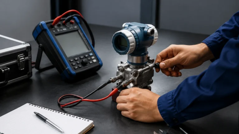
While the 5th edition allows for flexibility, a common industry baseline for Category 2 and Category 3 tanks is an annual proof test (every 12 months). However, many modern radar level meters feature "partial proof testing" capabilities, which allow for remote verification of the electronics and signal processing without requiring the liquid level to be raised or the sensor to be removed. This can supplement, but usually not replace, a full comprehensive proof test.
Technology Selection for Overfill Prevention Systems
Choosing the right technology directly impacts the ease and frequency of proof testing. The following table compares common instruments used in API 2350 compliant systems.
| Technology | Suitability for API 2350 | Maintenance Requirement | Proof-Testing Complexity |
| :— | :— | :— | :— |
| FMCW Radar | Excellent (Non-contact) | Low | Low (Supports remote testing) |
| Guided Wave Radar | Good (For small tanks) | Moderate | Moderate (Probe cleaning required) |
| Displacer/Float | Fair (Mechanical) | High | High (Requires physical movement) |
| Vibrating Fork | Excellent (Point level) | Low | Low (Simple wet/dry test) |
| Hydrostatic | Good (Continuous) | Moderate | Moderate (Requires calibration check) |

Installation Considerations for Reliable Proof Testing
To ensure that the api 2350 5th edition proof-testing frequency can be maintained without excessive downtime, installation must follow best practices:
1. Accessibility: Sensors should be installed where they can be safely accessed by technicians for manual verification if required. If the sensor is mounted on a tall tank (e.g., 20 meters), remote testing capabilities become a significant advantage.
2. Stilling Wells: For radar and ultrasonic sensors, using a stilling well can prevent signal interference from internal tank structures (ladders, agitators) and reduce surface turbulence, leading to more reliable high-level detection.
3. Independent Nozzles: The overfill prevention sensor must be installed in a separate nozzle from the primary inventory gauge to ensure true redundancy.
4. Environmental Protection: In outdoor installations, sunshades or heaters may be necessary to protect the electronics from extreme temperatures (e.g., above 60°C or below -40°C), which can impact the long-term reliability and testing intervals.
Limitations and Challenges
While API 2350 provides a robust framework, certain limitations must be recognized:
* Mechanical Wear: Mechanical switches and floats are prone to sticking due to wax buildup or corrosion in petroleum applications. This often necessitates a more frequent proof-testing schedule compared to solid-state electronic sensors.
* Vapor Space Interference: In high-pressure tanks or those containing liquids with high vapor pressure, the accuracy of non-contact sensors can be affected. The 5th edition requires that the chosen technology be compatible with the specific product properties under all operating conditions.
* Human Factor: For Category 1 and 2 tanks, the "system" includes the human operator. Proof testing in these cases must also include the testing of alarms, annunciators, and the communication protocols between the tank farm and the control center.
Frequently Asked Questions (FAQ)
Q: Does API 2350 5th Edition mandate a 12-month testing interval?
A: No, it does not mandate a specific 12-month interval for all tanks. It requires the owner/operator to establish a frequency based on risk, manufacturer guidance, and industry experience. However, an annual test is a widely accepted industry best practice.
Q: What is the difference between a functional test and a proof test?
A: A functional test checks if the device is powered and responding. A proof test is more comprehensive; it verifies that the device will perform its safety function (e.g., accurately detecting a high-high level and triggering an alarm) across its full required range.
Q: Can I use the same sensor for inventory and overfill prevention?
A: API 2350 generally requires an independent sensor for overfill prevention in Category 2 and 3 tanks to prevent a single point of failure from disabling both the monitoring and the safety systems.
Q: How does the 5th edition differ from the 4th edition regarding testing?
A: The 5th edition places a greater emphasis on the Management System (MS), requiring documented procedures for testing, training, and maintenance, aligning more closely with functional safety standards like ISA-84/IEC 61511.
Conclusion
Adhering to the API 2350 5th edition proof-testing frequency is a vital aspect of modern tank farm management. By combining reliable measurement technologies—such as radar and high-level switches—with a disciplined testing regimen, operators can significantly reduce the risk of catastrophic overfills. For engineers seeking reliable instrumentation that meets these rigorous standards, exploring the Main Page of professional level measurement manufacturers is the first step toward a compliant and safe facility.
Download API 2350 5th Edition Proof-testing Frequency as a PDF