API Rp 2350 5th Edition Sensor Independence Category 3 Tanks
API Rp 2350 5th Edition Sensor Independence Category 3 Tanks
In the realm of industrial tank farm management, the American Petroleum Institute (API) Recommended Practice (RP) 2350 stands as the definitive standard for overfill protection. With the release of the 5th edition, the industry saw a significant shift toward a more rigorous, risk-based approach to safety. One of the most critical aspects of this standard involves the requirements for Category 3 tanks, specifically regarding sensor independence. For engineers and facility managers, understanding how to implement api rp 2350 5th edition sensor independence category 3 tanks is essential for maintaining operational safety and regulatory compliance.
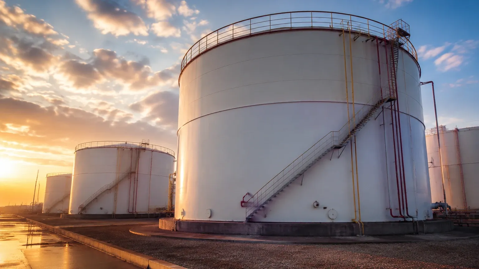
Overfill incidents in petroleum facilities can lead to catastrophic environmental damage, fire, and loss of life. To mitigate these risks, API RP 2350 categorizes tanks based on their level of automation and the presence of personnel. Category 3 tanks represent the highest tier of automated protection, requiring an Automatic Overfill Prevention System (AOPS) that operates independently of the standard tank gauging system.
Understanding API RP 2350 Tank Categories
Before delving into the specifics of sensor independence, it is necessary to define the three categories established by the standard:
1. Category 1 (Manual): These tanks rely on manual procedures and human intervention to prevent overfills. They require a high level of operator attention and are generally restricted to facilities with constant supervision.
2. Category 2 (Manual with Alarms): These tanks utilize a Basic Process Control System (BPCS) to provide alarms to an operator, who then takes manual action to stop the flow. While more advanced than Category 1, they still rely on human response.
3. Category 3 (Automatic): These tanks are equipped with an AOPS. In the event of a high-level condition, the system automatically triggers a shutdown or diversion of flow without the need for operator intervention.
For Category 3 tanks, the 5th edition of API RP 2350 emphasizes the necessity of a Safety Instrumented System (SIS) approach, often aligned with the IEC 61511 standard. The core of this safety loop is the independence of the sensors used for overfill prevention.
The Principle of Sensor Independence
Sensor independence is the cornerstone of a robust AOPS. In a Category 3 tank, the system must be designed so that a failure in the inventory management system (the BPCS) does not affect the ability of the safety system to detect an overfill condition.
Physical and Functional Separation
Independence is achieved through several layers:
* Separate Sensors: The sensor used for the High-High (HH) alarm and automatic shutdown must be physically distinct from the sensor used for continuous level monitoring or inventory control.
* Separate Power Sources: Ideally, the safety sensor should operate on a different power circuit or have dedicated surge protection to prevent a single electrical fault from disabling both the control and safety systems.
* Separate Logic Solvers: The signal from the safety sensor should be processed by a dedicated logic solver (such as a SIL-rated PLC) rather than the main plant DCS (Distributed Control System).
* Separate Final Elements: The safety system should actuate its own dedicated valve or pump-stop mechanism, ensuring that if a control valve sticks open, the safety valve can still close the line.
When evaluating hardware for these systems, many engineers start by reviewing the Main Page of specialized manufacturers to identify instruments that carry the necessary functional safety certifications (e.g., SIL 2 or SIL 3).
Measurement Principles for Category 3 Overfill Protection
Selecting the right technology for the independent sensor depends on the fluid properties, tank geometry, and environmental conditions. Below are the primary measurement principles used in API RP 2350 compliant systems.
1. Guided Wave Radar (GWR)
GWR utilizes Time Domain Reflectometry (TDR). A low-energy electromagnetic pulse is sent down a probe (waveguide). When the pulse hits the liquid surface, a portion of the energy is reflected back to the transmitter. The time-of-flight is used to calculate the level.
* Pros: Highly accurate; unaffected by vapor, foam, or turbulence.
* Role in Category 3: Often used as the primary safety sensor due to its high reliability and ability to provide continuous level data to the SIS.
2. Non-Contact Radar
This technology emits a microwave signal through the air. The reflection from the liquid surface is analyzed to determine the distance.
* Pros: No contact with the medium; suitable for corrosive or viscous fluids.
* Role in Category 3: Excellent for tanks where internal obstructions or the nature of the fluid make probes impractical.
3. Vibrating Tuning Fork (Point Level Switch)
A tuning fork is piezo-electrically energized to vibrate at its natural frequency. When the fork is submerged in liquid, the frequency changes, triggering an alarm.
* Pros: Extremely reliable for "High-High" detection; simple to install; low maintenance.
* Role in Category 3: Frequently used as a redundant, independent point-level switch to provide a final layer of protection alongside a continuous level transmitter.
4. Hydrostatic Pressure
This method measures the head pressure exerted by the liquid column. Since pressure is proportional to the height of the liquid and its density, the level can be calculated.
* Pros: Robust and well-understood technology.
* Role in Category 3: Used in applications where the liquid density is constant and top-mounting is not feasible.
Selection Table for Independent Sensors
| Technology | Accuracy | Suitability for Foam | Independence Strategy | Maintenance Requirement |
| :— | :— | :— | :— | :— |
| Guided Wave Radar | ±2 mm | Excellent | Continuous Safety Sensor | Low (Periodic Proof Test) |
| Non-Contact Radar | ±3 mm | Moderate | Continuous Safety Sensor | Low |
| Vibrating Fork | ±1 mm | Good | Point Level (HH Alarm) | Very Low |
| Ultrasonic | ±10 mm | Poor | Point Level / Continuous | Moderate (Clean Transducer) |
| Hydrostatic | ±0.1% FS | Excellent | Continuous Safety Sensor | Moderate (Calibration) |
Implementation Guidelines for Category 3 Tanks
Implementing api rp 2350 5th edition sensor independence category 3 tanks requires more than just buying two sensors. It requires a lifecycle management approach.
1. Risk Assessment
API RP 2350 5th Edition mandates a formal risk assessment for all tanks. This assessment determines the required Safety Integrity Level (SIL) for the AOPS. For most Category 3 tanks, a SIL 1 or SIL 2 rating is standard. The sensors chosen must be certified for use in these safety loops.
2. Redundancy vs. Diversity
While redundancy (using two of the same sensor) increases reliability, diversity (using two different technologies) reduces the risk of "common-cause failure." For example, if a specific chemical vapor interferes with a radar signal, having a vibrating fork switch as the independent safety sensor ensures the overfill will still be detected.
3. Proof Testing
A critical requirement of the 5th edition is the ability to perform proof tests. The independent sensor must be tested periodically to ensure it will function when called upon. Modern instruments often include "partial proof test" features that can be activated remotely, reducing the need for technicians to climb tanks.
4. Installation Considerations
* Nozzle Location: The independent safety sensor should be located in a different nozzle than the BPCS sensor. This prevents a single physical blockage or mechanical issue in one nozzle from affecting both sensors.
* Stilling Wells: If using radar in a tank with internal structures, a stilling well (a vertical pipe) can provide a clear signal path. However, the well must be properly vented to ensure the liquid level inside matches the level outside.
* Dead Zones: Every sensor has a "dead zone" or "blocking distance" at the very top of its range. When installing sensors for HH alarms, the mounting height must account for this dead zone to ensure the sensor can detect the liquid before it reaches the tank roof.
Common Risks and Limitations
Even with independent sensors, certain factors can compromise a Category 3 system:
* Inadequate Proof Testing: If the safety loop is not tested according to the prescribed interval, its probability of failure on demand (PFD) increases, effectively nullifying the Category 3 status.
* Bypassing the SIS: During maintenance or filling operations, operators might be tempted to bypass an AOPS that is triggering nuisance alarms. API RP 2350 requires strict administrative controls and logging for any bypasses.
* Environmental Interference: Heavy steam, extreme turbulence during high-fill rates, or dense foam can interfere with certain sensor types (like ultrasonic or non-contact radar). Selecting the correct technology for the specific medium is paramount.
* Density Variations: For hydrostatic sensors, significant changes in fluid density (e.g., switching from heavy crude to light distillate) will lead to inaccurate readings unless the system is recalibrated.
Frequently Asked Questions (FAQs)
Q: Can I use the same multi-variable transmitter for both control and safety?
A: No. API RP 2350 5th Edition explicitly requires sensor independence for Category 3. Even if a single device has two independent electronic outputs, a physical failure of the probe or the process connection would disable both functions. Separate physical instruments are required.
Q: Does every tank in a facility need to be Category 3?
A: Not necessarily. The category is determined by the facility type (attended vs. unattended) and a risk assessment. However, most modern petroleum terminals moving toward automation find Category 3 to be the safest and most efficient standard for high-turnover tanks.
Q: What is the difference between the 4th and 5th editions regarding Category 3?
A: The 5th edition places a much stronger emphasis on the management system and the integration of functional safety standards (IEC 61511). It clarifies the requirements for the AOPS and provides more detailed guidance on risk-based testing intervals.
Q: How do metric units apply to API 2350 compliance?
A: While API is a US-based organization, the standard is used globally. Engineering specifications typically use millimeters (mm) for level accuracy and meters (m) for tank height. For instance, a common requirement is that the HH alarm must be set at a level that allows for a response time of at least 5 to 10 minutes before an actual overfill occurs, based on the maximum fill rate in cubic meters per hour (m³/h).
Conclusion
Adhering to api rp 2350 5th edition sensor independence category 3 tanks is a rigorous but necessary process for modern industrial operations. By ensuring that the Automatic Overfill Prevention System is truly independent of the basic control system, facilities can significantly reduce the risk of environmental disasters and equipment damage.
Success lies in the careful selection of measurement technologies—be it Guided Wave Radar for continuous safety monitoring or Vibrating Fork switches for point-level detection—and a commitment to the lifecycle requirements of the Safety Instrumented System. For those looking to upgrade their facilities, consulting a comprehensive engineering reference and reviewing high-quality instrumentation options is the first step toward a safer, compliant operation.
Download API Rp 2350 5th Edition Sensor Independence Category 3 Tanks as a PDF