Coriolis Flow Meter Principle
Coriolis Flow Meter Principle
In the landscape of industrial process control, the ability to measure mass flow directly, rather than inferring it from volume, represents a significant leap in accuracy and reliability. The coriolis flow meter principle is the foundation of one of the most versatile and precise flow measurement technologies available today. Unlike volumetric flow meters, which are sensitive to changes in temperature, pressure, and fluid density, Coriolis meters provide a direct measurement of mass, making them the "gold standard" for custody transfer, chemical blending, and high-precision industrial automation.
Understanding the coriolis flow meter principle is essential for engineers and plant managers who require rigorous mass balance and inventory control. This guide explores the physics, mechanical design, and practical application of Coriolis technology, while also considering how these instruments integrate with broader level measurement systems for comprehensive process oversight.
The Physics of the Coriolis Effect
The fundamental coriolis flow meter principle is based on the Coriolis effect, first described by the French scientist Gaspard-Gustave de Coriolis in 1835. The effect refers to the inertial force exerted on an object moving within a rotating frame of reference.
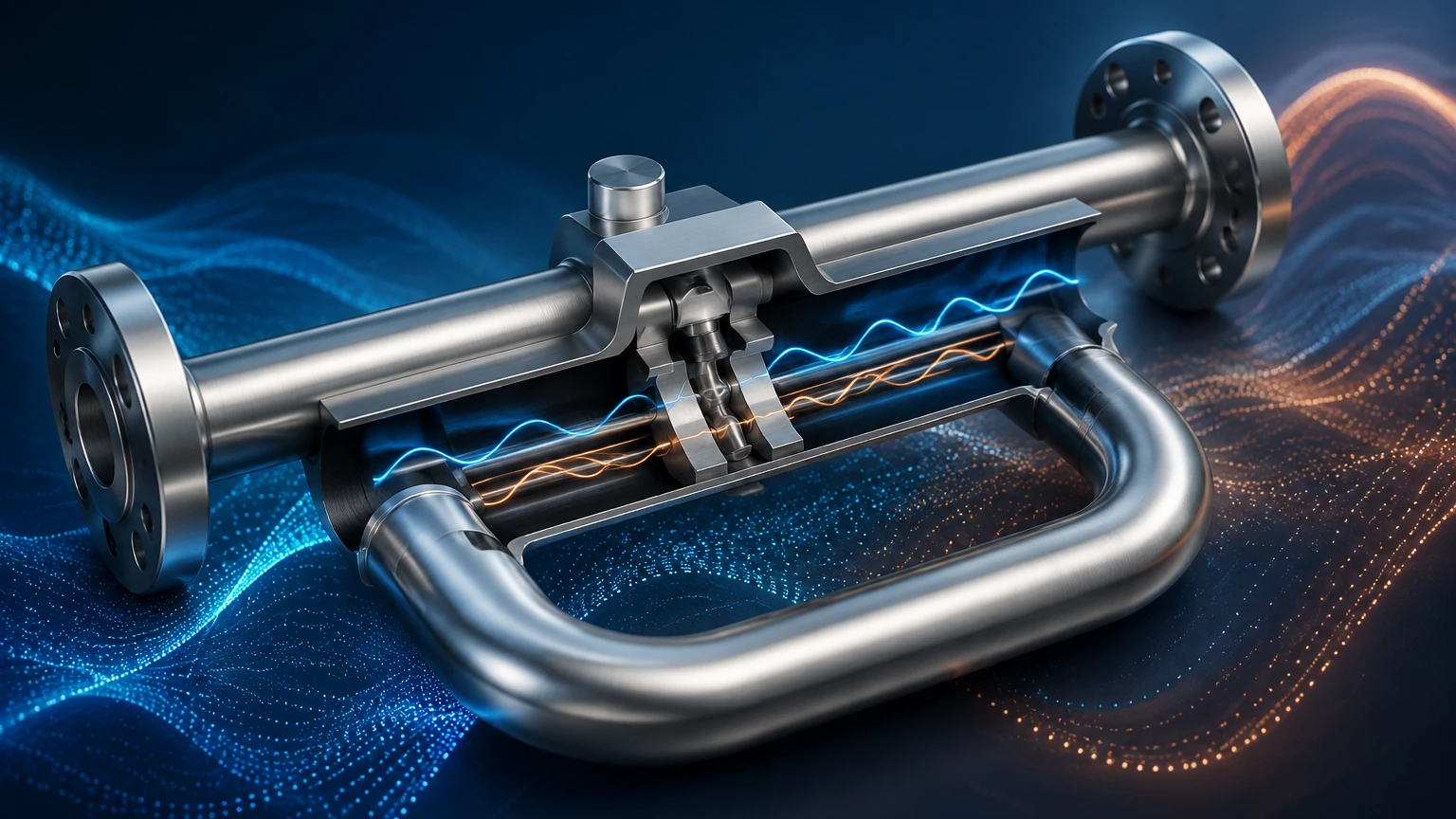
In an industrial Coriolis flow meter, this rotating frame is simulated by vibrating one or more flow tubes at their resonant frequency. When a fluid (liquid or gas) moves through these vibrating tubes, it is subjected to Coriolis forces. These forces act in opposite directions on the inlet and outlet sides of the tube, causing a minute distortion or "twist" in the tube's shape.
Mathematically, the Coriolis force ($F_c$) is expressed as:
$$F_c = -2m(\omega \times v)$$
Where:
* $m$ is the mass of the fluid.
* $\omega$ is the angular velocity (vibration).
* $v$ is the velocity of the fluid within the tube.
Because the force is directly proportional to the mass ($m$), measuring the resulting tube distortion allows the instrument to calculate the mass flow rate with extreme precision, independent of the fluid's physical properties.
Mechanical Design and Components
A Coriolis flow meter consists of two primary components: the sensor (the wetted part) and the transmitter (the electronics). The sensor's internal geometry is critical to how the coriolis flow meter principle is applied in different environments.
Flow Tube Geometries
Most Coriolis meters utilize either a U-shaped tube or a straight-tube design.
* U-Shaped Tubes: These are highly sensitive and can measure very low flow rates. The curved geometry allows for significant displacement even with minimal force, though they can be more difficult to drain and may require more space for installation.
* Straight Tubes: These are preferred for applications involving high-viscosity fluids or those that require "Clean-in-Place" (CIP) capabilities. They offer lower pressure drops and are less prone to clogging, though they require more sophisticated electronics to detect the smaller vibrations.
Drive Coil and Pick-off Sensors
The drive coil is responsible for inducing the vibration in the tubes, typically at a frequency of 80 to 1000 Hz. Pick-off sensors (usually electromagnetic) are located at the inlet and outlet sections of the tube. These sensors detect the position of the tube over time, generating a sine wave signal.
How It Works: Phase Shift and Mass Flow
To understand the coriolis flow meter principle in action, one must look at the relationship between the signals generated by the pick-off sensors.
1. Zero Flow State: When the fluid is stationary, the tubes vibrate uniformly. The sine waves generated by the inlet and outlet pick-off sensors are perfectly in phase.
2. Flowing State: As fluid begins to move, the Coriolis force causes the inlet side of the tube to resist the vibration (lagging) and the outlet side to accelerate the vibration (leading). This creates a "twist" in the tube.
3. Phase Shift Calculation: The electronics measure the time difference (delta-T) between the two sine waves. This time delay is known as the phase shift.
The mass flow rate is directly proportional to this phase shift. Because the measurement is based on time and frequency, it is inherently digital and highly resistant to signal drift. Modern transmitters can process these signals to provide accuracies as high as ±0.05% for liquids.
Multivariable Capabilities: Density and Temperature
One of the unique advantages of the coriolis flow meter principle is that it allows for the simultaneous measurement of multiple process variables.
Density Measurement
The tubes in a Coriolis meter vibrate at their natural resonant frequency. This frequency is determined by the mass of the tube and the mass of the fluid inside it. If the fluid density changes, the total mass changes, which in turn shifts the resonant frequency. By monitoring this frequency, the meter can calculate the fluid's density in real-time. This is particularly useful in the chemical industry for monitoring concentrations or identifying different products in a multi-product pipeline.
Temperature Measurement
Since the elasticity of the flow tubes changes with temperature, Coriolis meters include an internal Resistance Temperature Detector (RTD). This sensor measures the tube temperature to compensate for structural changes, but the data is also provided as an output for process monitoring.
Practical Selection Criteria
Choosing a Coriolis meter requires balancing accuracy requirements against fluid characteristics and installation constraints. The following table provides a reference for evaluating these instruments.
| Feature | Consideration | Engineering Impact |
| :— | :— | :— |
| Accuracy | Typically 0.1% to 0.05% | Critical for high-value fluids and custody transfer. |
| Turndown Ratio | Often 100:1 or higher | Allows for accurate measurement across a wide range of flow rates. |
| Material Selection | 316L Stainless Steel, Hastelloy, Tantalum | Must be compatible with corrosive process fluids. |
| Pressure Drop | Varies by tube diameter and shape | U-tubes generally have higher pressure drops than straight tubes. |
| Fluid State | Liquid, Gas, or Slurry | Entrained gas in liquids (slug flow) can disrupt measurements. |
| Line Size | 1 mm to 300 mm (typical) | Larger sizes become significantly more expensive and heavy. |
Installation Considerations and Best Practices
While Coriolis meters are robust, their reliance on high-frequency vibration means that installation environment is crucial. To ensure the coriolis flow meter principle is applied effectively, engineers should follow these guidelines:
* Vibration Isolation: The meter should be isolated from external pipeline vibrations. High-frequency noise from pumps or valves can interfere with the drive frequency of the meter.
* Orientation: For liquid applications, the tubes should ideally point downward (in a U-shape) to prevent gas bubbles from being trapped. For gas applications, the tubes should point upward to prevent condensate buildup. Straight tubes are often installed vertically to facilitate self-draining.
* Zero Calibration: After installation and under full-pipe, zero-flow conditions, a "zero trim" must be performed. This accounts for any mechanical stresses imposed on the meter by the piping.
* Stress-Free Mounting: The meter must not be used to pull misaligned pipes together. Mechanical stress on the sensor body can cause measurement errors or even structural failure of the tubes over time.
Limitations and Common Challenges
Despite their precision, Coriolis meters are not universal solutions.
1. Initial Cost: The capital expenditure for a Coriolis meter is significantly higher than for electromagnetic or ultrasonic meters, especially in larger line sizes.
2. Entrained Gas: Small amounts of gas in a liquid stream (and vice versa) can cause the tubes to vibrate erratically. This is known as "damping." While modern digital signal processing (DSP) can mitigate some of this, high gas fractions can lead to measurement suspension.
3. Size and Weight: In sizes above 150 mm (6 inches), Coriolis meters become extremely heavy and require specialized support structures.
Integration with Level Measurement Systems
In many industrial applications, flow measurement and level measurement are used together to provide a complete picture of material movement. For instance, in a chemical storage tank, a radar level meter provides the primary inventory data. However, for precise batching or loading operations, a Coriolis meter is used at the inlet or outlet.
By comparing the mass flow data from the Coriolis meter with the volume/level data from instruments like those found on the Main Page, operators can detect leaks, verify fluid density, and ensure that tanks are not overfilled. This synergy between flow and level technology is vital for safety and efficiency in water treatment, oil and gas, and chemical processing.
Frequently Asked Questions
Q: Can Coriolis meters measure gas flow?
A: Yes, the coriolis flow meter principle applies to gases as well as liquids. However, because gases have much lower density, the Coriolis forces generated are smaller, requiring more sensitive electronics and often resulting in lower accuracy compared to liquid applications.
Q: Does the viscosity of the fluid affect the accuracy?
A: Generally, no. One of the primary benefits of Coriolis technology is that it is independent of Reynolds number and viscosity. It can measure everything from water to heavy crude oil and adhesives without recalibration.
Q: How often do Coriolis meters need recalibration?
A: Because there are no moving parts in the fluid stream (no bearings or gears), Coriolis meters are extremely stable. Many facilities only perform a calibration check every 2 to 5 years, depending on the criticality of the application and local regulations.
Conclusion
The coriolis flow meter principle provides an unparalleled method for direct mass flow measurement, offering multivariable data that includes density and temperature. While the technology requires a higher initial investment and careful installation, the long-term benefits of accuracy, reduced maintenance, and process stability make it an essential tool for modern industrial automation. For engineers looking to optimize their process, integrating high-precision flow data with reliable level measurement is the key to achieving operational excellence. To explore a wide range of level measurement solutions that complement mass flow systems, Review product options and application support.