Water Tank Level Control
Water Tank Level Control
In industrial and municipal engineering, water tank level control is a fundamental process required to ensure operational continuity, safety, and resource efficiency. Whether managing potable water reservoirs, cooling tower basins, or industrial process tanks, the ability to accurately monitor and regulate fluid levels prevents costly overflows, protects pumps from dry-running, and maintains the required hydraulic head for downstream processes.
Welk provides a comprehensive suite of measurement technologies designed to meet the rigorous demands of water tank level control. Selecting the appropriate instrumentation requires a deep understanding of the physical principles of measurement, the environmental conditions of the installation, and the specific requirements of the control logic. This guide serves as a practical engineering reference for selecting and implementing level measurement solutions across various water-related applications.
Core Measurement Technologies and Principles
Before selecting a control system, engineers must understand the physical principles that govern different level measurement sensors. Each technology offers distinct advantages depending on the tank geometry and the characteristics of the water being measured.
Ultrasonic Level Measurement (Non-Contact)
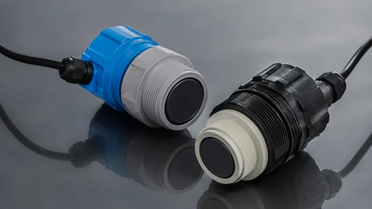
Ultrasonic sensors operate on the Time-of-Flight (ToF) principle. The sensor emits a high-frequency acoustic pulse from a piezoelectric transducer. This pulse travels through the air, reflects off the water surface, and returns to the sensor. The distance is calculated using the formula:
Distance = (Speed of Sound × Time) / 2
Because the speed of sound is affected by air temperature, modern ultrasonic sensors include integrated temperature compensation. These sensors are ideal for clean water applications and open channels where the sensor does not need to touch the liquid, reducing maintenance requirements. However, they can be affected by heavy foam, steam, or significant turbulence which may scatter the acoustic signal.
Radar Level Measurement (Non-Contact)
Radar level meters also use the ToF principle but employ electromagnetic waves (typically in the 26GHz or 80GHz range) rather than sound. Radar waves are unaffected by air temperature, pressure, or vacuum conditions.
* Pulse Radar: Sends discrete microwave pulses and measures the time taken for the return.
* FMCW (Frequency Modulated Continuous Wave): Transmits a continuous signal with a varying frequency. The difference in frequency between the transmitted and received signal is proportional to the distance.
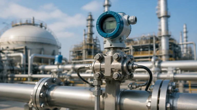
Radar is the preferred choice for high-precision water tank level control, especially in outdoor tanks subject to wind or temperature fluctuations, or in tanks where condensation and vapor are present.
Hydrostatic Pressure Measurement (Contact)
Hydrostatic level transmitters measure the pressure exerted by the liquid column above the sensor. The relationship is defined by the formula:
P = ρ × g × h
Where *P* is pressure, *ρ* (rho) is the fluid density, *g* is gravity, and *h* is the height of the liquid. For water tank level control, submersible pressure transducers are often lowered to the bottom of the tank, or flange-mounted transmitters are installed at the tank base. This method is highly reliable for deep reservoirs and is unaffected by surface foam or surface turbulence.
Magnetic Level Gauges and Switches
Magnetic level gauges utilize a float containing an internal magnet that moves with the water level inside a bypass chamber. This float interacts with external flags or a transmitter to provide visual and electronic feedback. For simple point-level control (e.g., high-level alarms or low-level pump shut-off), float switches or conductivity probes are often used as redundant safety measures alongside continuous transmitters.
Selection Criteria for Water Tank Level Sensors
Choosing the right instrument for water tank level control involves evaluating several technical parameters. Engineers should consult the Main Page of the equipment manufacturer to review specific model specifications against the following criteria:
1. Tank Geometry and Height: Shallow tanks (under 2 meters / 6.5 feet) may require sensors with small "dead zones" or blocking distances. Deep reservoirs (over 15 meters / 50 feet) often favor hydrostatic or high-power radar units.
2. Water Characteristics: Potable water requires food-grade materials (e.g., 316L Stainless Steel or specialized plastics). Wastewater or greywater may contain solids or corrosive chemicals, necessitating non-contact sensors or chemically resistant diaphragms.
3. Environmental Conditions: Outdoor tanks are subject to direct sunlight, lightning, and extreme temperature swings. Sensors must have appropriate Ingress Protection (IP) ratings, typically IP67 or IP68, and surge protection.
4. Accuracy Requirements: For simple inventory monitoring, an accuracy of ±10mm (0.4 inches) may suffice. For precise dosing or custody transfer, high-frequency radar units offering ±1mm (0.04 inches) accuracy are required.
5. Output and Integration: Most industrial systems require a 4-20mA signal, often with HART protocol for remote diagnostics. For modern automation, Modbus RTU or Profibus may be preferred.
Practical Selection Table for Water Tank Applications
The following table provides a general guideline for selecting technology based on common water tank scenarios.
| Application Type | Recommended Technology | Advantages | Limitations |
| :— | :— | :— | :— |
| Potable Water Reservoir | Ultrasonic or Radar | Non-contact, hygienic | Sensitive to heavy condensation (Ultrasonic) |
| Wastewater / Sump | Hydrostatic (Submersible) | Robust, easy installation | Build-up on sensor face over time |
| Chemical Storage (Dosing) | Radar (80GHz) | High precision, chemical resistance | Higher initial cost |
| Small Process Tank | Ultrasonic | Cost-effective, compact | Not suitable for pressurized tanks |
| Deep Wells / Boreholes | Hydrostatic (Slim-line) | Works in narrow spaces | Requires atmospheric venting cable |
| Boiler Feed Water | Guided Wave Radar | Handles high temp/pressure | Contact-based, potential for scaling |
Installation Best Practices and Engineering Considerations
Proper installation is as critical as sensor selection for reliable water tank level control. Even the most advanced sensor will fail to provide accurate data if installed incorrectly.
Avoiding the "Dead Zone"
Every non-contact sensor has a "dead zone" (also called a blocking distance) directly beneath the transducer face. If the water level rises into this zone, the sensor will report an error or an incorrect reading. Always mount the sensor high enough so that the maximum water level remains below the dead zone boundary.
Positioning and Obstructions
Sensors should be mounted away from the tank walls to prevent false reflections (side-lobe interference). A general rule for ultrasonic and radar sensors is to mount the unit at least 200mm (8 inches) away from the wall for every 1 meter (3.3 feet) of tank height. Additionally, sensors must be positioned away from:
* Inlet Pipes: Falling water creates turbulence and air bubbles that scatter signals.
* Agitators/Mixers: Moving blades cause significant signal noise.
* Ladders and Brackets: Internal structures can cause "ghost" echoes.
Venting and Pressure
For hydrostatic transmitters, the sensor must be referenced to atmospheric pressure to compensate for changes in barometric pressure. This is usually achieved through a small vent tube inside the signal cable. Ensure this tube is not kinked and is protected from moisture by a desiccant filter.
Managing Risks and Limitations in Level Control Systems
While modern instrumentation is highly reliable, engineers must account for potential risks in the system design.
* Signal Interference: In metal tanks, multiple reflections can occur. Using high-frequency (80GHz) radar with a narrow beam angle can mitigate this risk.
* Condensation and Build-up: In humid environments, water droplets can form on the sensor face. Some Welk radar units feature a "drip-off" antenna design or PTFE coatings to prevent water accumulation from attenuating the signal.
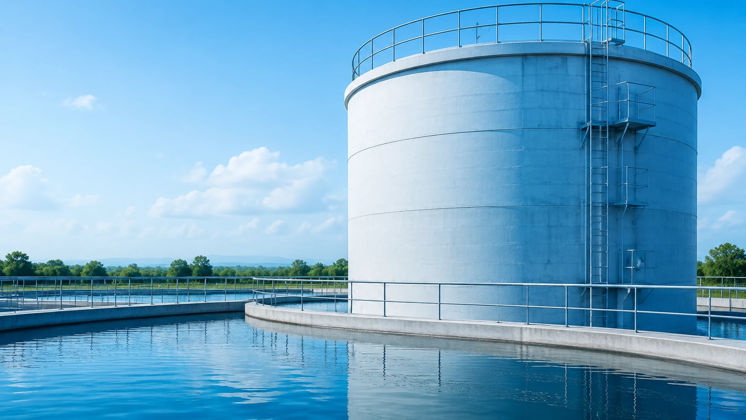
* Lightning and Surges: Outdoor water tanks are often the highest point in a facility, making them targets for lightning. Use shielded cables and dedicated surge protection devices (SPDs) at both the sensor and the PLC/controller end.
* Redundancy: For critical applications, such as fire water storage, it is standard practice to use two different technologies (e.g., an ultrasonic transmitter for continuous level and a mechanical float switch for a high-level alarm). This "diversity in measurement" ensures that a failure in one technology does not lead to a system-wide failure.
Frequently Asked Questions (FAQs)
Q: Can I use an ultrasonic sensor in a pressurized water tank?
A: Generally, no. Ultrasonic waves depend on air density to travel. If the pressure changes significantly, the speed of sound changes, leading to large errors. Radar or hydrostatic sensors are better suited for pressurized vessels.
Q: How often do water tank level sensors need calibration?
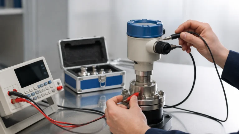
A: This depends on the technology. Hydrostatic sensors may drift slightly over years and should be checked annually. Radar and ultrasonic sensors are solid-state and rarely drift, but the "zero" and "span" settings should be verified during routine maintenance cycles.
Q: What is the best way to monitor water levels in a tank located in a remote area?
A: For remote locations, low-power sensors with Modbus outputs can be paired with cellular or LoRaWAN gateways. Hydrostatic sensors are often favored here due to their low power consumption and ease of deployment.
Q: Does the material of the tank (plastic vs. steel) affect the sensor choice?
A: Yes. Radar signals can pass through plastic tank tops, allowing for "top-down" measurement without cutting a hole in the tank. Metal tanks require a mounting flange or threaded connection and reflect radar signals much more strongly.
Conclusion
Effective water tank level control is a balance of selecting the right physics for the environment and following rigorous installation standards. By utilizing technologies like radar, ultrasonic, and hydrostatic measurement, operators can achieve high levels of precision and reliability. For detailed product specifications and application support, engineers should evaluate the full range of industrial instruments available on the manufacturer's Main Page to ensure the selected solution meets the specific technical requirements of their project.}