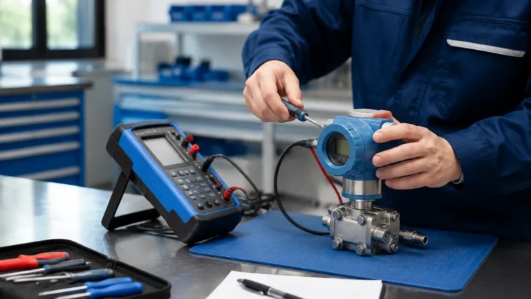
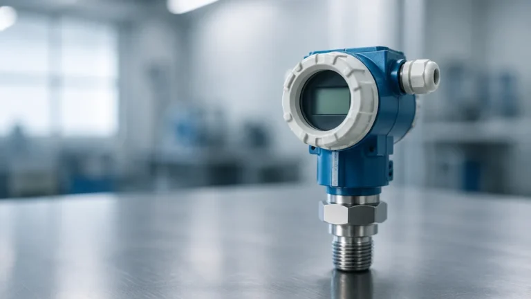
Bubbler Flow Meter
Bubbler Flow Meter
In the field of industrial fluid dynamics and wastewater management, measuring flow in open channels presents unique challenges. Unlike closed-pipe systems where magnetic or ultrasonic flow meters are standard, open channels—such as flumes, weirs, and partially filled pipes—require a level-based approach to determine flow rates. One of the most robust and time-tested technologies for this application is the bubbler flow meter.
By utilizing the principles of hydrostatic pressure, a bubbler flow meter provides a non-contact sensing method (at the transducer level) that is particularly effective in harsh environments where traditional sensors might fail. This guide explores the measurement principles, selection criteria, and installation best practices for bubbler flow systems in industrial B2B applications.
Measurement Principles of Bubbler Systems
The operation of a bubbler flow meter is based on the relationship between hydrostatic pressure and liquid level. While the system is often referred to as a "flow meter," it is technically a level measurement device that calculates flow based on the known geometry of a primary flow element, such as a Parshall flume or a V-notch weir.
The Physics of Bubbling
To measure the level, a small-diameter tube (the dip tube) is submerged into the liquid at a fixed depth. A regulated compressed air source (or inert gas) is forced through this tube. As the air escapes the bottom of the tube in the form of bubbles, the pressure inside the tube increases until it equals the hydrostatic pressure exerted by the liquid column above the tube's outlet.
The pressure ($P$) is directly proportional to the depth ($h$) of the liquid and its density ($
ho$):
$$P = \rho \cdot g \cdot h$$
Where:
* P is the backpressure measured by the transducer.
* ρ is the density of the liquid (typically water, ~1000 kg/m³).
* g is the acceleration due to gravity (~9.81 m/s²).
* h is the height of the liquid above the tube outlet.
From Level to Flow
Once the level ($h$) is determined, the bubbler’s internal controller applies a mathematical formula specific to the primary flow element installed in the channel. For example, a V-notch weir follows a specific power-law equation where flow ($Q$) is proportional to $h^{2.5}$. By accurately measuring the backpressure, the system provides a continuous readout of the flow rate in units such as liters per second (L/s) or cubic meters per hour (m³/h).
For engineers seeking comprehensive instrumentation for these applications, it is essential to Review product options and application support to ensure the selected transducer matches the required precision of the primary flow element.
Key Components of a Bubbler Flow Meter
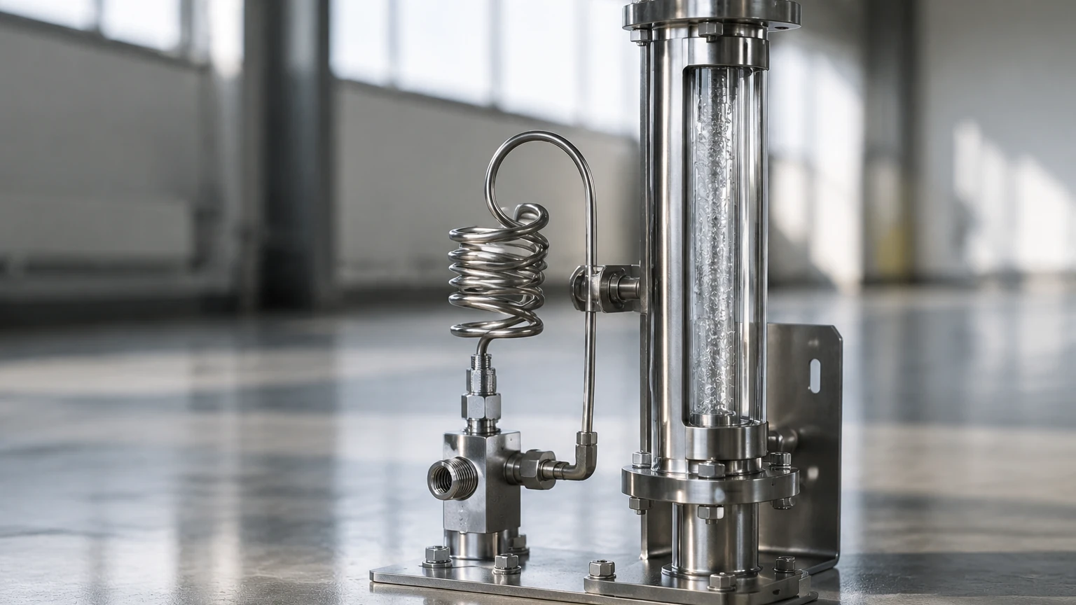
A complete bubbler flow measurement system consists of several critical sub-assemblies:
1. Air Supply/Compressor: Provides the pressurized medium. In remote locations, small internal diaphragm pumps are used. In industrial plants, regulated plant air is often utilized.
2. Pressure Regulator and Needle Valve: These components ensure a constant, low flow rate of air (typically 1 to 3 bubbles per second). A constant flow is vital to prevent pressure spikes that could skew readings.
3. Dip Tube (Sensing Line): Usually made of stainless steel, PVC, or PTFE, depending on the chemical composition of the fluid. It must be rigidly mounted to prevent movement.
4. Pressure Transducer: A high-precision sensor that converts the air backpressure into an electrical signal (4-20mA or digital output).
5. Flow Computer/Controller: The intelligence of the system that performs the level-to-flow conversion and manages data logging.
Selection Criteria for Industrial Applications
Choosing the right bubbler system requires an evaluation of the fluid properties and the physical constraints of the installation site. Use the following table as a preliminary selection guide:
| Feature | Requirement / Consideration | Recommendation |
| :— | :— | :— |
| Fluid Type | High solids, fats, or grease | Use a high-rate purge or large diameter dip tube |
| Chemical Corrosivity | Acids, bases, or solvents | Select PTFE or Hastelloy dip tubes |
| Measurement Range | 0 to 3 meters (Standard) | Standard low-pressure transducer |
| Accuracy Needs | High (Custody transfer) | Precision pressure transducer with temperature compensation |
| Power Availability | Remote/Solar | Low-power diaphragm pump with sleep modes |
| Air Quality | Plant air vs. Ambient | Use air dryers and oil filters for plant air |
| Ambient Temperature | Sub-zero conditions | Heat-traced sensing lines to prevent freezing |
Installation Considerations
Proper installation is the most significant factor in the long-term reliability of a bubbler flow meter. Unlike ultrasonic sensors, which are mounted above the flow, the bubbler dip tube is in direct contact with the process.
Dip Tube Placement
The dip tube must be located in a "stilled" area of the flow, typically upstream of the weir or flume at a distance of 3 to 4 times the maximum head height. This prevents turbulence from causing erratic pressure readings. The tube should be mounted vertically, though a slight angle can sometimes help prevent sediment buildup in the tip.
Preventing Clogs
In wastewater applications, the primary risk is the accumulation of solids at the tip of the dip tube. To mitigate this:
* Automatic Purge: Some systems include a "blow-down" or high-pressure purge cycle that periodically clears the tube of obstructions.
* Tube Cut: Cutting the end of the dip tube at a 45-degree angle can help bubbles release more cleanly and reduce the surface area available for debris to cling to.
Calibration and Zeroing
Initial calibration involves "zeroing" the system. This is done by ensuring the pressure transducer reads zero when the liquid level is exactly at the "zero flow" point of the weir or flume (the crest of the weir or the floor of the flume).
Advantages and Limitations
Advantages
* Immune to Surface Conditions: Bubbler flow meters are unaffected by foam, steam, surface turbulence, or floating debris, which often cause ultrasonic sensors to lose signal.
* Hazardous Area Compatibility: Since the electronic components (transducer and controller) can be located far from the actual measurement point, only the pneumatic tube enters the hazardous or corrosive zone.
* Durability: There are no moving parts or sensitive electronics submerged in the fluid.
Limitations
* Air Supply Dependency: The system requires a continuous, reliable source of clean air. If the air supply fails, the measurement is lost.
* Maintenance of Tubing: Sensing lines can leak or become pinched, leading to significant measurement errors.
* Lag Time: In very long sensing lines (over 50 meters), there may be a slight delay in response to rapid level changes.
Comparison: Bubbler vs. Other Technologies
When designing a flow monitoring station, engineers often compare bubblers with ultrasonic or radar level sensors.
| Technology | Best For | Main Weakness |
| :— | :— | :— |
| Bubbler | Foamy liquids, high steam, deep wells | Requires air supply; tube maintenance |
| Ultrasonic | Clean water, easy access | Sensitive to foam, wind, and temperature gradients |
| Radar | High precision, non-contact | Higher cost; affected by narrow channel geometry |
| Hydrostatic (Submersible) | Deep tanks, consistent density | Sensor is submerged; prone to fouling in wastewater |
Maintenance and Troubleshooting
To ensure the accuracy of a bubbler flow meter, a routine maintenance schedule should be established.
1. Check for Leaks: Even a microscopic leak in the air line will cause the pressure to drop, resulting in a lower-than-actual flow reading. Use a soap solution on joints periodically.
2. Inspect the Dip Tube: Check for bio-growth or mineral scaling at the tip. In hard water applications, calcium deposits can gradually constrict the opening.
3. Moisture Traps: If using a compressor, ensure that moisture traps are drained. Water in the sensing line can cause "slugs" that create oscillating readings.
Common FAQs
Q: Can a bubbler flow meter be used in a closed pipe?
A: Only if the pipe is partially filled and vented to the atmosphere (acting as an open channel). It is not suitable for pressurized closed-pipe flow.
Q: How does liquid density affect the reading?
A: Since the system measures pressure, a change in liquid density (e.g., from high salt concentration) will change the backpressure for the same level. If the density is not 1.0 (water), the controller must be programmed with the specific gravity of the fluid.
Q: What is the maximum distance between the controller and the dip tube?
A: While systems can operate at distances up to 100 meters (330 feet), it is recommended to keep the distance under 30 meters (100 feet) to minimize lag time and potential leak points.
Conclusion
The bubbler flow meter remains a vital tool for industrial process control and environmental monitoring. Its ability to provide reliable data in the presence of foam, steam, and debris makes it a preferred choice for wastewater treatment plants and chemical processing facilities. By understanding the hydrostatic principles and adhering to strict installation guidelines regarding dip tube placement and air supply quality, engineers can implement a robust flow measurement solution that withstands the rigors of industrial environments.
For those integrating these systems into broader automation frameworks, visiting the Main Page of specialized manufacturers like Welk can provide further insights into how bubbler technology fits alongside modern radar and ultrasonic level measurement suites.