Calibration of Pressure Transducer
Calibration of Pressure Transducer
In the landscape of industrial automation and process control, the accuracy of level measurement often depends on the precision of pressure-sensing instruments. For industries ranging from water treatment to chemical processing, the hydrostatic level transmitter is a staple tool. However, the reliability of these devices is only as good as their last calibration. The calibration of pressure transducer units is a fundamental maintenance task that ensures the electrical output of a sensor accurately represents the physical pressure—and by extension, the liquid level—within a system.
Welk, as a professional manufacturer of industrial level measurement instruments, emphasizes that even the highest-quality radar level meters or hydrostatic transmitters require a structured approach to verification. This guide provides a comprehensive technical overview of the principles, procedures, and practical considerations involved in the calibration of pressure transducer devices used in industrial environments.
Understanding the Measurement Principle
Before diving into calibration procedures, it is essential to understand how these transducers function. In the context of level measurement, most pressure transducers operate on the principle of hydrostatic pressure. According to Pascal’s Law, the pressure at the bottom of a liquid column is directly proportional to the height of the liquid and its density. The formula is expressed as:
P = ρ × g × h
Where:
* P is the hydrostatic pressure (Pa or bar).
* ρ (rho) is the density of the liquid (kg/m³).
* g is the acceleration due to gravity (approximately 9.81 m/s²).
* h is the height of the liquid column (meters).
Transducer Technologies
Most modern transducers utilize one of two primary technologies to convert this physical force into an electrical signal:
1. Piezoresistive Sensors: These contain a diaphragm with integrated strain gauges. When pressure is applied, the diaphragm deforms, changing the electrical resistance of the gauges. This change is processed into a standard 4-20mA or 0-10V signal.
2. Capacitive Sensors: These measure the change in capacitance between a flexible sensing diaphragm and a rigid reference electrode. As pressure moves the diaphragm, the capacitance changes, which the internal electronics convert into a readable output.
Calibration ensures that the relationship between the input pressure and the output signal remains linear and accurate across the device's entire operating range.
The Critical Importance of Calibration
Why is the calibration of pressure transducer units so vital? Over time, all electronic sensors experience "drift." This is a gradual shift in the sensor’s output caused by environmental factors, mechanical fatigue, or electronic component aging.
In B2B industrial applications, inaccurate readings can lead to:
* Safety Risks: Overfilling tanks containing hazardous chemicals can lead to environmental disasters or workplace injuries.
* Economic Loss: Inaccurate inventory measurement in oil and gas applications can result in significant financial discrepancies.
* Process Inefficiency: In water treatment, incorrect level data can cause pumps to run dry or valves to actuate at the wrong time, increasing energy consumption and wear on equipment.
Regular calibration cycles verify that the instrument still meets its original manufacturer specifications, providing peace of mind and regulatory compliance.
Step-by-Step Guide to the Calibration of Pressure Transducer
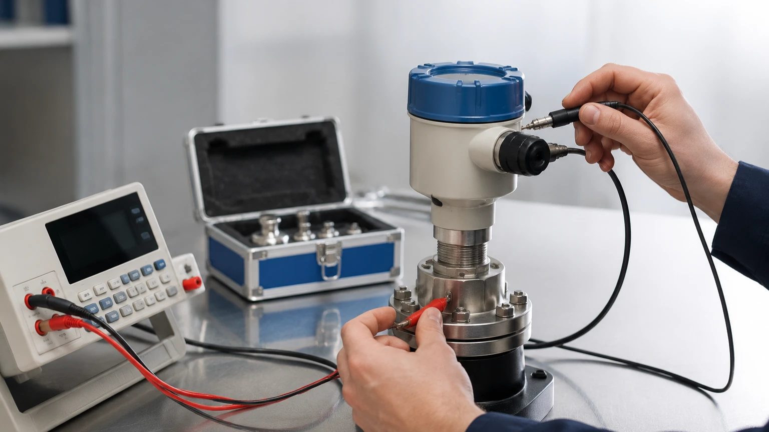
Calibration involves comparing the output of the "Device Under Test" (DUT) against a traceable reference standard with a significantly higher degree of accuracy (typically at least four times more accurate than the DUT).
1. Preparation and Safety
Ensure the transducer is isolated from the process. In a hydrostatic level application, this usually involves closing the process valves and venting any residual pressure. Clean the diaphragm carefully, as any buildup of debris or calcification can interfere with the calibration results.
2. Equipment Setup
You will typically need:
* A Pressure Source: A manual hand pump or a deadweight tester.
* A Reference Gauge: A high-precision digital pressure calibrator.
* A Multimeter: To measure the 4-20mA output loop.
* Power Supply: To power the transducer during the test (usually 24V DC).
3. The Five-Point Calibration Method
The industry standard for the calibration of pressure transducer units is the five-point check. This involves testing the device at 0%, 25%, 50%, 75%, and 100% of its full-scale range, both ascending and descending.
* Zero Adjustment: With no pressure applied (atmospheric pressure for gauge sensors), the output should be exactly 4.000 mA. If it is not, adjust the "Zero" screw or digital parameter until it is correct.
* Span Adjustment: Apply the maximum rated pressure for the application (e.g., 1.0 bar for a 10-meter water tank). The output should be 20.000 mA. Adjust the "Span" or "Gain" accordingly.
* Linearity Check: Test the intermediate points (25%, 50%, 75%). For a 4-20mA sensor, 50% pressure should yield exactly 12.000 mA. If the intermediate points are off while zero and span are correct, the sensor may have linearity issues, often requiring factory repair or replacement.
4. Hysteresis Testing
By checking the points while decreasing the pressure, you can identify hysteresis—the difference in output for the same pressure point depending on whether the pressure was increasing or decreasing. High hysteresis often indicates a damaged or fatigued diaphragm.
Calibration Selection and Comparison
Choosing the right transducer and calibration frequency depends on the specific demands of your application. The following table provides a general comparison for industrial selection.
| Feature | Submersible Hydrostatic | External Pressure Transducer | Differential Pressure (DP) |
| :— | :— | :— | :— |
| Primary Use | Open wells, sumps, reservoirs | Side-mounted tank level | Pressurized vessels |
| Calibration Ease | Moderate (requires removal) | Easy (via manifold) | Complex (requires 3-valve manifold) |
| Typical Accuracy | 0.25% to 0.5% FS | 0.1% to 0.25% FS | 0.075% to 0.1% FS |
| Maintenance | High (fouling risk) | Low | Moderate |
| Calibration Frequency | Annually | Every 1-2 years | Every 6-12 months |
For engineers seeking high-precision instruments for these applications, consulting the Main Page of a specialized manufacturer like Welk provides access to technical specifications and support for various sensor types.
Installation Considerations for Long-Term Accuracy
Proper installation is the first step in ensuring a transducer stays in calibration for as long as possible.
* Venting: For gauge pressure sensors, the back of the diaphragm must be vented to the atmosphere. Ensure the vent tube (often integrated into the cable) is not kinked and is protected by a moisture-wicking filter.
* Temperature Effects: Pressure transducers are sensitive to temperature fluctuations. While most high-quality Welk sensors include internal temperature compensation, installing the sensor away from direct heat sources or using cooling siphons for steam applications is recommended.
* Mounting Position: Always calibrate the transducer in the same orientation in which it will be installed. Gravity can affect the diaphragm of highly sensitive low-pressure sensors, leading to a "position error" if calibrated horizontally but installed vertically.
* Pressure Snubbers: In systems prone to water hammer or pressure spikes, install a snubber to protect the delicate sensing element from mechanical shock, which can permanently shift the calibration.
Limitations and Common Risks
While calibration can correct for many errors, it cannot fix fundamental hardware failures.
1. Non-Linearity: If a sensor is accurate at 0% and 100% but significantly off at 50%, it is non-linear. This is usually a sign of internal electronic failure or physical damage to the sensing element.
2. Zero Drift vs. Span Drift: Zero drift (the whole curve shifting up or down) is common and easily corrected. Span drift (the slope of the curve changing) is more serious and often indicates aging components.
3. Media Compatibility: Using a transducer with a 316L stainless steel diaphragm in a highly corrosive acid environment will lead to diaphragm thinning. This changes the mechanical properties of the sensor, making calibration impossible and eventually leading to total failure.
Frequently Asked Questions (FAQs)
Q: How often should the calibration of pressure transducer units be performed?
A: For most industrial applications, an annual calibration is standard. However, in critical safety systems or harsh environments with high vibration and temperature swings, semi-annual or quarterly checks may be necessary.
Q: Can I calibrate a pressure transducer using water instead of a specialized pump?
A: While a water column can be used to generate pressure for low-range sensors (1 meter of water ≈ 0.098 bar), it is difficult to maintain precision. Professional digital pressure calibrators or deadweight testers are preferred for B2B industrial standards.
Q: What is the difference between a "Zero Trim" and a full calibration?
A: A zero trim is a quick adjustment to the 4mA point to account for atmospheric changes or installation orientation. A full calibration involves checking multiple points across the entire range to ensure linearity and span accuracy.
Q: Does a change in liquid density affect the calibration?
A: The pressure transducer measures pressure, not level directly. If the density of the liquid in your tank changes (e.g., due to temperature or chemical concentration), the pressure reading will change even if the level remains the same. In these cases, the level calculation logic in the PLC must be updated, rather than recalibrating the transducer itself.
Conclusion
The calibration of pressure transducer instruments is a cornerstone of effective industrial process management. By understanding the underlying physics of hydrostatic measurement and following a rigorous five-point calibration protocol, facilities can ensure the longevity and accuracy of their level measurement systems. Whether utilizing submersible sensors for water treatment or high-precision transmitters for chemical processing, the commitment to regular verification minimizes risk and optimizes operational efficiency. For further technical details on selecting the right sensor for your specific environment, visit the Main Page for comprehensive product data and engineering support.