Capacitance Fuel Level Sensor
Capacitance Fuel Level Sensor
In the landscape of industrial fluid management, the capacitance fuel level sensor represents a critical technology for high-precision, solid-state monitoring. Unlike traditional mechanical float switches, which are prone to wear and tear due to moving parts, capacitance-based systems leverage electrical properties to provide continuous level data. This technology is particularly prevalent in sectors requiring high reliability, such as diesel generator monitoring, fleet management, and industrial fuel storage. For engineers and procurement specialists, understanding the underlying physics and selection criteria is essential for ensuring long-term operational accuracy.
Measurement Principles of Capacitive Sensors
The operation of a capacitance fuel level sensor is rooted in the basic physics of an electrical capacitor. A capacitor consists of two conductive plates separated by an insulating material known as a dielectric. The ability of this setup to store an electrical charge is defined as capacitance ($C$).
In a fuel level measurement application, the sensor probe (usually a stainless steel rod or tube) acts as one electrode, while the tank wall (if metallic and grounded) acts as the second electrode. If the tank is non-conductive, a second concentric tube or a reference wire is integrated into the sensor design to serve as the second electrode. The fuel within the tank serves as the dielectric material.
The Role of the Dielectric Constant
The fundamental formula for capacitance is:
$$C = \epsilon_0 \epsilon_r \frac{A}{d}$$
Where:
* $C$ is the capacitance.
* $\epsilon_0$ is the permittivity of free space.
* $\epsilon_r$ is the relative permittivity (dielectric constant) of the material between the electrodes.
* $A$ is the area of the electrodes.
* $d$ is the distance between the electrodes.
Since the geometry ($A$ and $d$) of the sensor is fixed, the capacitance varies only with the change in the average dielectric constant of the medium between the electrodes. Air has a dielectric constant of approximately 1.0, while most hydrocarbon fuels (diesel, gasoline, kerosene) have a dielectric constant ranging from 1.9 to 2.2. As the fuel level rises, it displaces the air between the probe and the reference electrode. Because the fuel has a higher dielectric constant than air, the total measured capacitance increases linearly with the liquid level. The internal electronics of the sensor then convert this change in capacitance into a standard industrial signal, such as 4-20mA, 0-5V, or RS485 Modbus.
Key Components and Construction
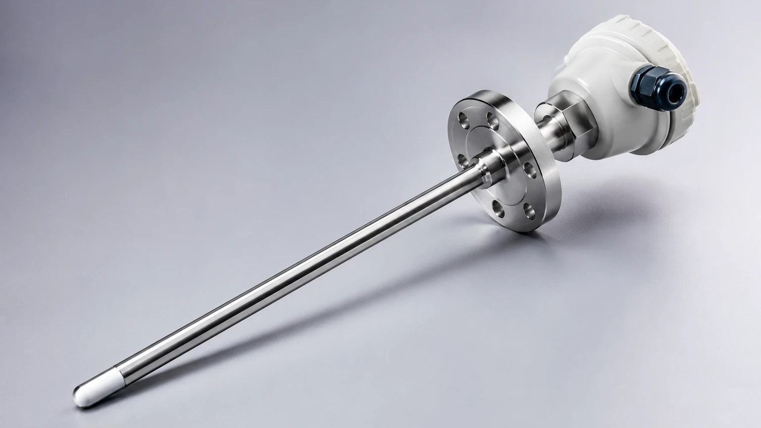
A professional-grade capacitance fuel level sensor, such as those produced by Welk, is engineered to withstand harsh chemical environments and mechanical vibrations. The primary components include:
1. The Probe: Typically constructed from 316L stainless steel or aluminum. In cases where the fuel may contain corrosive additives, the probe may be coated with PTFE (Teflon) or FEP to provide insulation and chemical resistance.
2. The Electronic Module: Located in the sensor head, this circuitry performs signal conditioning, temperature compensation, and linearizing. High-quality sensors include EMI/RFI shielding to prevent interference from nearby industrial machinery.
3. Process Connection: The threaded or flanged interface that secures the sensor to the tank. Common sizes include G1/2", G1", or 1.5" NPT.
4. Sealing: High-performance O-rings (Viton or Fluorosilicone) are used to prevent fuel leakage and protect the electronics from moisture ingress (IP67 or IP68 ratings).
Technical Selection Criteria
Selecting the correct capacitance fuel level sensor requires a detailed analysis of the application environment. Engineers must confirm the following parameters before procurement:
Tank Material and Geometry
If the tank is made of plastic or fiberglass, a standard single-rod probe will not function because there is no conductive return path. In these instances, a coaxial probe (also known as a concentric tube sensor) must be used. The outer tube provides a consistent ground reference regardless of the tank material or shape.
Fuel Type and Dielectric Stability
Capacitance sensors are highly effective for fuels with stable dielectric constants. However, if the fuel type changes frequently (e.g., switching between different biofuel blends), the sensor may require recalibration. Biodiesel, for instance, has a higher dielectric constant than standard petroleum diesel. For a comprehensive overview of how different sensors handle various media, users can consult the Main Page of Welk's technical catalog.
Temperature and Pressure
Standard industrial fuel sensors are rated for temperatures between -40°C and +85°C. For high-temperature applications, such as heavy fuel oil (HFO) heating tanks, specialized high-temperature versions with remote electronics are required to protect the circuitry from thermal degradation.
Practical Selection Table
| Fuel Type | Dielectric Constant (εr) | Recommended Probe Type | Typical Accuracy |
| :— | :— | :— | :— |
| Standard Diesel | 2.1 | Rod or Coaxial | ±0.5% to ±1% |
| Gasoline | 1.9 – 2.0 | Coaxial (for safety/stability) | ±1% |
| Jet Fuel (A1) | 2.1 | Coaxial | ±0.5% |
| Biodiesel (B20) | 2.3 – 2.5 | Coaxial (coated) | ±1% |
| Heavy Fuel Oil | 2.5 – 3.0 | Heavy-duty Rod (coated) | ±2% |
Installation Considerations
Proper installation is paramount to the accuracy of a capacitance fuel level sensor. Unlike ultrasonic sensors, which require a clear line of sight through the air, capacitance sensors are contact-based and must be physically submerged in the medium.
1. Vertical Alignment: The sensor should be installed vertically. If the tank is mobile (e.g., on a vehicle), the sensor should ideally be located in the center of the tank to minimize the effects of fuel sloshing on level readings.
2. Avoidance of Obstructions: The probe must not touch the tank walls or any internal baffles. A minimum clearance of 30mm to 50mm is generally recommended for rod-style probes to avoid "bridge" capacitance or short-circuiting.
3. Grounding: For metallic tanks, ensuring a low-resistance electrical bond between the sensor housing and the tank body is critical. Poor grounding is the leading cause of signal drift in capacitance systems.
4. Dead Zones: Most sensors have a small "dead zone" at the very top (near the threads) and the very bottom (the tip of the probe). This must be accounted for when calculating the usable volume of the tank.
Calibration Procedures
Most modern capacitance fuel level sensors feature a "Full" and "Empty" calibration routine. This process maps the measured capacitance at zero fuel and maximum fuel to the desired output signal (e.g., 4mA and 20mA).
* Zero Calibration: Performed when the tank is empty or the sensor is in the air. This sets the baseline capacitance.
* Span Calibration: Performed when the tank is at its maximum desired level. This accounts for the specific dielectric constant of the fuel currently in use.
Some advanced digital sensors allow for "dry calibration," where the dielectric constant is entered manually into the software, though "wet calibration" remains the gold standard for precision.
Limitations and Common Risks
While highly reliable, capacitance fuel level sensors are not universal solutions. Engineers should be aware of the following limitations:
* Conductive Contaminants: The presence of water in a fuel tank is a significant risk. Water has a dielectric constant of approximately 80, which is nearly 40 times higher than diesel. Even a small amount of water at the bottom of the tank can cause the sensor to report a much higher fuel level than actually exists. In systems where water contamination is likely, water-bottom sensors or fuel-water separators should be used in conjunction with the level sensor.
* Coating and Buildup: If the fuel is heavy or contains waxes that solidify on the probe, the sensor may continue to detect the "coating" even after the fuel level has dropped. PTFE-coated probes are the standard solution to minimize material adhesion.
* Tank Deformation: In large plastic tanks, the walls may bulge when full. If the tank wall is being used as the second electrode, this change in distance ($d$) will alter the capacitance and introduce errors. Coaxial probes eliminate this risk entirely.
Comparison with Alternative Technologies
| Feature | Capacitance | Ultrasonic | Hydrostatic (Pressure) |
| :— | :— | :— | :— |
| Moving Parts | None | None | None |
| Contact | Yes | No | Yes |
| Foam Sensitivity | Low | High | None |
| Accuracy | High | Medium | Medium |
| Cost | Moderate | Moderate | Low to Moderate |
| Best Use Case | Precision fuel tracking | Non-contact chemical storage | Deep underground tanks |
Frequently Asked Questions (FAQs)
Q: Can I cut the sensor probe to length?
A: Many industrial capacitance sensors are designed to be field-cuttable. However, this usually requires a recalibration of the electronics afterward, as shortening the probe changes the base capacitance. Always check the manufacturer's manual before cutting.
Q: Does the sensor work in pressurized tanks?
A: Yes, capacitance sensors are well-suited for pressurized environments because they do not rely on atmospheric pressure or sound waves. However, the process connection and seals must be rated for the specific pressure of the vessel.
Q: How often should a capacitance fuel level sensor be recalibrated?
A: In stable environments with consistent fuel quality, recalibration is typically only needed once a year during routine maintenance. If the fuel source or blend changes significantly, immediate recalibration is advised.
Q: Is the sensor safe for flammable fuels?
A: For gasoline or other Class I liquids, the sensor must be used with an intrinsically safe (IS) barrier or be housed in an explosion-proof enclosure. Ensure the sensor carries relevant certifications such as ATEX, IECEx, or UL for hazardous areas.
Conclusion
The capacitance fuel level sensor remains a cornerstone of industrial level measurement due to its lack of moving parts and high sensitivity to hydrocarbon liquids. By understanding the dielectric properties of the fuel and selecting the appropriate probe configuration—whether rod or coaxial—operators can achieve precise and maintenance-free monitoring. For further technical specifications and to explore a wide range of measurement solutions, visit the Main Page for expert guidance and product support.