Open Channel Flow Measurement
Open Channel Flow Measurement
Open channel flow measurement is a critical process in industrial and municipal water management, environmental monitoring, and irrigation systems. Unlike closed-pipe systems where fluid is under pressure, open channel flow occurs when the liquid has a free surface exposed to the atmosphere. Measuring the volume of liquid passing through these channels—such as flumes, weirs, or partially filled pipes—requires a combination of hydraulic engineering principles and precise level sensing technology.
For engineers and plant managers, selecting the right instrumentation is essential for regulatory compliance, billing accuracy, and process optimization. This guide explores the fundamental principles, primary and secondary measurement devices, and the practical considerations necessary for successful implementation.
Understanding the Principles of Open Channel Flow
The measurement of flow in an open channel is typically an indirect process. Rather than measuring velocity directly (though some systems do), the most common method relies on the relationship between the liquid level (head) and the flow rate. This is achieved by placing a standardized hydraulic structure, known as a primary device, into the channel.
The Level-to-Flow Relationship
When a primary device like a weir or flume is installed, it creates a predictable restriction in the flow. This restriction causes the liquid level upstream to rise in a specific proportion to the flow rate. The mathematical relationship can generally be expressed by the formula:
Q = C × Hⁿ
Where:
* Q is the flow rate.
* C is a discharge coefficient unique to the geometry of the primary device.
* H is the measured head (liquid level).
* n is an exponent that varies based on the type of device (e.g., 1.5 for rectangular weirs, 2.5 for V-notch weirs).
Because the flow rate is exponentially related to the head, even a small error in level measurement can result in a significant error in the calculated flow. This makes the choice of the secondary device—the level sensor—paramount. For a detailed look at the sensors used to capture these measurements, you can visit the Main Page of our technical catalog.
Primary Measurement Devices: Flumes and Weirs
Primary devices are the physical structures that provide the known geometry required to calculate flow. They are categorized into two main types: weirs and flumes.
Weirs
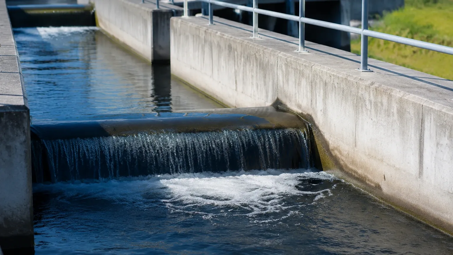
A weir is essentially a dam or obstruction placed across the channel. The liquid flows over the top of the weir (the crest). Weirs are highly accurate for clean water applications but have limitations in industrial settings.
* V-Notch Weirs: Best for measuring low flow rates with high precision. Common angles include 22.5°, 45°, 60°, and 90°.
* Rectangular Weirs: Used for higher flow rates. They can be suppressed (spanning the full width of the channel) or contracted.
* Limitations: Weirs cause a significant "head loss" (a drop in the liquid's energy) and tend to trap sediment and debris behind the weir plate, which can alter the measurement over time.
Flumes
Flumes are shaped man-made channels that restrict the flow area or change the channel slope. They are generally preferred for industrial wastewater and sewer systems because they are self-cleaning.
* Parshall Flumes: The most widely used flume globally. It is versatile and handles a wide range of flow rates.
* Palmer-Bowlus Flumes: Designed specifically to be installed in existing circular pipes or U-shaped channels, making them ideal for sewer manholes.
* Khafagi Flumes: Often used in European applications for wastewater treatment plants.
* Advantages: Flumes produce less head loss than weirs and can handle higher velocities and suspended solids without clogging.
Secondary Measurement Devices: Level Sensing Technologies
The secondary device is the instrument that measures the liquid level (H) and converts it into a flow signal (Q). Modern industrial level meters utilize several different technologies to achieve this.
Ultrasonic Level Sensors
Ultrasonic sensors are the most common choice for open channel flow measurement. They work by emitting a high-frequency sound pulse that reflects off the liquid surface. The time-of-flight is measured to determine the distance.
* Pros: Non-contact, easy to install, and cost-effective.
* Cons: Accuracy can be affected by air temperature fluctuations, heavy foam on the liquid surface, or high winds in outdoor installations.
Radar Level Meters
Radar technology, specifically non-contacting microwave radar, is becoming the preferred high-end solution. It operates similarly to ultrasonic sensors but uses electromagnetic waves instead of sound.
* Pros: Not affected by temperature, wind, or steam. It provides extremely high precision and is ideal for volatile or steaming industrial effluents.
* Cons: Higher initial cost than ultrasonic sensors.
Hydrostatic Level Transmitters
These sensors measure the pressure exerted by the liquid column above them. They are submerged at a fixed point in the channel.
* Pros: Unaffected by surface foam or turbulence.
* Cons: Contact-based, meaning they are susceptible to fouling, corrosion, or damage from debris in the flow stream.
Selection Criteria for Industrial Applications
Choosing the right combination of primary and secondary devices requires an evaluation of the specific site conditions. The following table provides a comparison of the most common technologies used in open channel flow measurement.
| Feature | Ultrasonic Sensors | Radar Level Meters | Hydrostatic Transmitters |
| :— | :— | :— | :— |
| Measurement Type | Non-contact (Sound) | Non-contact (Microwave) | Contact (Pressure) |
| Accuracy | Good (±0.25% of range) | Excellent (±2mm) | Moderate (±0.5% of span) |
| Surface Foam | Poor (Absorbs signal) | Moderate (Can penetrate) | Excellent (Ignores foam) |
| Steam/Vapor | Poor (Distorts sound) | Excellent (Unaffected) | Excellent (Unaffected) |
| Maintenance | Low | Very Low | Moderate (Cleaning required) |
| Cost | Low to Moderate | Moderate to High | Low |
Installation Best Practices and Geometric Requirements
Even the most accurate sensor will fail if the installation does not adhere to hydraulic standards. The goal is to measure the head at a point where the flow is laminar (smooth) and not turbulent.
1. Sensor Placement: The level sensor must be installed at a specific distance upstream from the primary device. For a Parshall flume, this is typically at a point 2/3 of the length of the converging section. For weirs, it should be at a distance of at least 3 to 4 times the maximum head (H max) upstream from the weir plate.
2. Dead Band Considerations: Every non-contact sensor has a "dead band" or "blanking distance" (usually 0.2m to 0.5m). The sensor must be mounted high enough so that even at maximum flow, the liquid does not enter this zone.
3. Stilling Wells: In channels with significant turbulence or surface ripples, a stilling well—a vertical pipe connected to the channel—can be used to provide a calm surface for the sensor to measure.
4. Leveling: The primary device must be perfectly level both longitudinally and transversely. A tilted flume or weir will introduce significant errors into the flow calculation.
Limitations and Environmental Challenges
Engineers must be aware of several factors that can compromise the integrity of open channel flow measurement:
* Submergence: If the downstream water level rises too high, it can back up into the primary device. This is known as a "submerged flow" condition. While some flumes can compensate for this, it generally reduces accuracy significantly.
* Approach Conditions: The flow entering the primary device must be straight and tranquil. Bends, gates, or drops immediately upstream can cause turbulence and uneven velocity distribution.
* Sedimentation: In low-velocity channels, solids may settle at the base of the primary device. Regular inspection is required to ensure the geometry of the channel remains unchanged.
* Temperature Gradients: For ultrasonic sensors, a significant difference between the liquid temperature and the air temperature can create a "thermocline," which bends the sound waves and causes false readings. Using sensors with integrated temperature compensation is vital.
Frequently Asked Questions (FAQ)
Q: How often should open channel flow systems be calibrated?
A: Regulatory bodies often require annual calibration. However, for internal process control, a semi-annual check of the primary device's dimensions and a manual measurement of the head to verify the sensor's accuracy is recommended.
Q: Can I measure flow in a pipe that is only partially full?
A: Yes. This is still considered open channel flow. You can use a Palmer-Bowlus flume or an area-velocity meter that measures both the level and the speed of the liquid.
Q: What is the difference between "Head" and "Level"?
A: In this context, they are often used interchangeably. "Head" specifically refers to the depth of the liquid above a reference point (the crest of a weir or the floor of a flume) that contributes to the pressure driving the flow.
Q: Is radar always better than ultrasonic?
A: Not necessarily. While radar is more robust against environmental factors like wind and steam, modern ultrasonic sensors are highly effective for most municipal wastewater applications and are more budget-friendly.
Conclusion
Successful open channel flow measurement depends on the synergy between hydraulic design and electronic precision. By understanding the limitations of weirs and flumes and selecting the appropriate level sensing technology—whether it be radar, ultrasonic, or hydrostatic—operators can ensure reliable data for their most critical applications. For professionals seeking high-quality instrumentation and customized OEM/ODM services, exploring the available Main Page resources is the first step toward an optimized measurement solution. Confirming the specific chemical compatibility of your fluid and the expected flow ranges with a technical specialist will ensure the longevity and accuracy of your installation.