Type of Rtd Sensor
Type of Rtd Sensor
In the realm of industrial process control, accurate temperature measurement is as critical as pressure or level monitoring. Resistance Temperature Detectors (RTDs) are among the most reliable instruments used to capture precise temperature data. For engineers managing complex systems—such as those found on the Main Page of industrial instrumentation providers—understanding the specific type of rtd sensor required for a given application is essential for maintaining system integrity and measurement accuracy.
RTDs operate on a fundamental physical principle: the electrical resistance of a metal increases as its temperature rises. This predictable relationship allows for highly repeatable and stable measurements over long periods. In applications like hydrostatic level measurement, temperature data is often used to compensate for fluid density changes, ensuring that level readings remain accurate despite thermal fluctuations. This article provides a technical overview of the various types of RTD sensors, their construction, wiring configurations, and selection criteria.
Understanding the Measurement Principle of RTD Sensors
The core of every RTD is a sensing element made from a pure metal, typically platinum, nickel, or copper. These metals possess a Positive Temperature Coefficient (PTC), meaning their resistance increases in a linear or near-linear fashion with temperature.
The relationship between resistance ($R$) and temperature ($T$) is defined by the Callendar-Van Dusen equation for platinum RTDs. For most industrial purposes, a simplified linear approximation is used:
$$R_t = R_0 [1 + \alpha(t – t_0)]$$
Where:
* $R_t$ is the resistance at temperature $t$.
* $R_0$ is the resistance at a reference temperature (usually 0°C).
* $\alpha$ is the temperature coefficient of resistance (the "Alpha" value).
For a standard Pt100 sensor, $R_0$ is 100 ohms at 0°C, and the alpha value is typically 0.00385 $\Omega/\Omega/°C$. By measuring the resistance across the element, a transmitter or controller can calculate the exact temperature of the process medium.
Classification by Sensing Element Material
The most common way to categorize a type of rtd sensor is by the material used in the sensing element. Each material offers a different balance of temperature range, sensitivity, and cost.
1. Platinum (Pt)
Platinum is the industry standard for RTDs due to its exceptional stability, oxidation resistance, and wide temperature range. It is used in the well-known Pt100 and Pt1000 sensors.
* Temperature Range: -200°C to +850°C.
* Advantages: High accuracy, excellent repeatability, and chemically inert.
* Applications: Critical chemical processes, laboratory standards, and high-temperature industrial exhausts.
2. Nickel (Ni)
Nickel sensors are less expensive than platinum and offer a higher change in resistance per degree (higher sensitivity).
* Temperature Range: -60°C to +250°C.
* Advantages: High sensitivity makes it easier to detect small temperature changes.
* Limitations: Non-linear resistance-temperature curve at higher temperatures; prone to oxidation.
3. Copper (Cu)
Copper is used primarily for its excellent linearity across a narrow temperature range.
* Temperature Range: -100°C to +150°C.
* Advantages: Very linear relationship; low cost.
* Limitations: Low base resistance (typically 10 ohms), which makes it susceptible to lead wire resistance errors.
Structural Variations: Thin-Film vs. Wire-Wound RTDs
Beyond the material, the physical construction of the sensing element determines how the sensor responds to environmental stressors like vibration and thermal shock.
Thin-Film RTDs
Thin-film elements are produced by depositing a microscopic layer of platinum onto a ceramic substrate, which is then laser-trimmed to the desired resistance. This layer is protected by a thin coating of glass.
* Pros: Highly resistant to vibration, faster response times due to low mass, and cost-effective for mass production.
* Cons: Slightly lower temperature range than wire-wound types (usually capped at 500°C).
Wire-Wound RTDs
These consist of a fine platinum wire coiled around a ceramic or glass mandrel. The coil is housed inside a protective tube to prevent mechanical damage.
* Pros: Highest accuracy and stability; capable of reaching the upper limits of platinum’s temperature range (850°C).
* Cons: Very fragile and susceptible to damage from industrial vibration; higher manufacturing costs.
Wiring Configurations and Their Impact on Accuracy
Because an RTD is a resistance-based device, the resistance of the lead wires connecting the sensor to the control system can introduce significant errors. Choosing the correct wiring type of rtd sensor is vital for precision.
2-Wire RTDs
This is the simplest configuration, using two wires to connect the sensor. However, the resistance of these lead wires is added directly to the sensor's resistance, leading to an artificially high temperature reading.
* Use Case: Only suitable when the lead wires are very short (under 3 meters) or where high accuracy is not required.
3-Wire RTDs
This is the most common configuration in industrial automation and level measurement systems. It uses a third wire to measure the lead resistance and subtract it from the total resistance.
* Use Case: Standard for industrial processes where the distance between the sensor and the transmitter is moderate.
4-Wire RTDs
Used primarily in laboratories and high-precision calibration, the 4-wire configuration completely eliminates the effect of lead wire resistance by using two wires to carry the excitation current and two separate wires to measure the voltage drop across the element.
* Use Case: High-accuracy applications where lead wire length or temperature fluctuations along the cable would otherwise compromise the data.
Selection Criteria for Industrial Applications
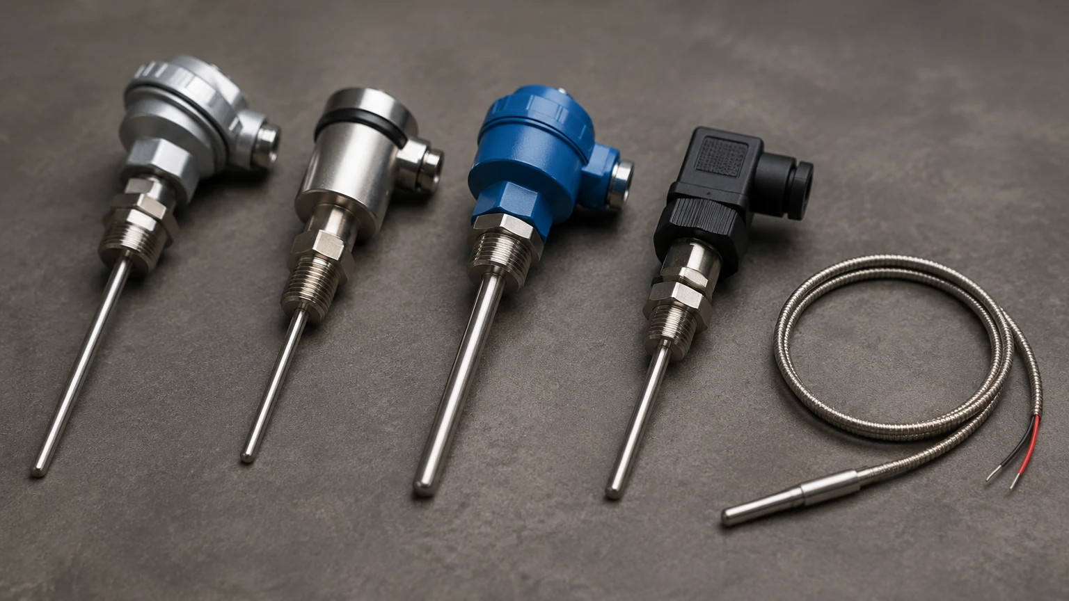
When selecting a type of rtd sensor for a project, engineers must balance technical requirements with budgetary constraints. The following table provides a quick reference for selection:
| Criteria | Platinum (Pt100/Pt1000) | Nickel (Ni120) | Copper (Cu10) |
| :— | :— | :— | :— |
| Temperature Range | -200°C to 850°C | -60°C to 250°C | -100°C to 150°C |
| Accuracy | High (Class AA to B) | Moderate | Moderate |
| Linearity | Excellent | Poor | Excellent |
| Stability | Excellent | Fair | Good |
| Vibration Resistance | High (Thin-film) | Moderate | Moderate |
| Common Use | General Industrial | HVAC Systems | Motor Windings |
For integrated level measurement solutions, such as those found on the Main Page, RTDs are often embedded within the probe assembly of a hydrostatic transmitter or a magnetic level gauge to provide real-time density correction.
Installation Guidelines and Protection
To ensure the longevity of an RTD sensor, proper installation is paramount. Industrial environments often expose sensors to high pressures, corrosive chemicals, and mechanical stress.
1. Thermowells: In most liquid level and pressure applications, the RTD should not be exposed directly to the process media. A thermowell (a metal sleeve) is installed into the tank or pipe, allowing the sensor to be inserted or removed without breaching the process seal. This also protects the sensor from high flow rates and corrosive fluids.
2. Immersion Depth: To avoid errors caused by heat conduction through the sensor sheath (stem conduction), the RTD must be immersed deep enough into the medium. A general rule is an immersion depth of at least 10 times the diameter of the protective sheath.
3. Transmitter Location: For long-distance signal transmission, it is recommended to use a head-mounted transmitter. This converts the resistance signal into a 4-20mA or digital (HART/Modbus) signal at the point of measurement, minimizing lead wire interference.
Limitations and Operational Risks
While RTDs are highly accurate, they are not without limitations. Engineers should be aware of the following risks:
* Self-Heating: To measure resistance, a small current must be passed through the sensor. This current generates heat ($I^2R$). If the current is too high, the sensor will read higher than the actual process temperature. Most modern transmitters limit this current to less than 1mA to minimize this effect.
* Response Time: RTDs generally have a slower response time compared to thermocouples, especially when housed in heavy-duty thermowells. This must be accounted for in fast-acting control loops.
* Mechanical Fragility: Wire-wound elements are particularly sensitive to shock. In applications with high-frequency vibration, thin-film RTDs or specialized vibration-resistant builds are required.
* Cost: Compared to thermocouples, RTDs (especially platinum types) are more expensive, particularly for high-temperature ranges.
Frequently Asked Questions (FAQs)
Q: What is the difference between Pt100 and Pt1000?
A: The number refers to the resistance in ohms at 0°C. A Pt100 has 100 ohms, while a Pt1000 has 1000 ohms. Pt1000 sensors are often preferred in battery-powered or low-power applications because they require less current, and the higher base resistance makes lead wire resistance errors less significant in 2-wire setups.
Q: Can I use an RTD for temperatures above 1000°C?
A: No. Platinum RTDs are generally limited to 850°C. For temperatures exceeding this, thermocouples (such as Type K or Type S) are the preferred technology.
Q: How often should an RTD be calibrated?
A: While RTDs are very stable, annual calibration is recommended for critical processes. If the sensor is subjected to severe thermal cycling or mechanical shock, more frequent checks may be necessary.
Q: Why is my RTD reading "Open" or "Off-scale High"?
A: This usually indicates a break in the sensing element or a disconnected lead wire. Because the resistance becomes infinite when the circuit is broken, the controller interprets this as an extremely high temperature.
By carefully selecting the appropriate type of rtd sensor and following rigorous installation standards, industrial operators can ensure reliable data for their process control and level measurement systems. For more information on integrated measurement technologies, visit the Main Page for detailed product specifications and application support.