Carbon Dioxide Storage
Carbon Dioxide Storage
Carbon dioxide storage is a critical component of modern industrial processes, particularly within the framework of Carbon Capture, Utilization, and Storage (CCUS) initiatives. As industries strive to reduce their environmental footprint, the demand for efficient, safe, and highly accurate monitoring of stored CO2 has increased. Whether stored as a refrigerated liquid in insulated tanks or as a supercritical fluid in high-pressure vessels, managing the inventory of carbon dioxide requires a deep understanding of both the physical properties of the gas and the instrumentation used to measure it.
In industrial settings, carbon dioxide storage typically involves maintaining the substance in a liquid state to maximize density and minimize volume. This is often achieved through high-pressure vessels or cryogenic tanks. For engineers and plant operators, selecting the correct level measurement technology is paramount to ensuring operational safety, preventing overfills, and maintaining precise inventory control. This article provides a technical overview of measurement principles, technology comparisons, and practical considerations for CO2 storage applications.
Measurement Principles for CO2 Level Monitoring
Before selecting a specific instrument for carbon dioxide storage, it is essential to understand the physical principles that govern level measurement. Carbon dioxide presents unique challenges due to its low dielectric constant, potential for phase changes, and the high-pressure environments required for its storage.
Time-of-Flight (ToF) Principle
Radar and ultrasonic sensors operate on the Time-of-Flight principle. The sensor emits a signal (electromagnetic for radar, acoustic for ultrasonic) that travels to the surface of the liquid CO2 and reflects back to the receiver. The distance is calculated based on the time elapsed and the speed of the wave in the medium. In the context of carbon dioxide storage, radar is generally preferred over ultrasonic because the speed of sound is highly dependent on gas composition and pressure, which can fluctuate in CO2 tanks.
Hydrostatic Pressure Principle
This method measures the pressure exerted by the liquid column at the bottom of the tank. Since pressure is directly proportional to the height of the liquid and its density ($P = \rho gh$), the level can be inferred. However, because the density of liquid CO2 changes significantly with temperature and pressure, hydrostatic transmitters must be paired with temperature compensation to maintain accuracy.
Buoyancy and Magnetic Coupling
Magnetic level gauges utilize a float containing a magnet that rises and falls with the liquid level. This float is coupled with an external indicator or a transmitter. This mechanical principle is robust and provides a clear visual indication without requiring a power source for the local display, which is advantageous for safety-critical carbon dioxide storage systems.
Comparing Level Measurement Technologies for CO2
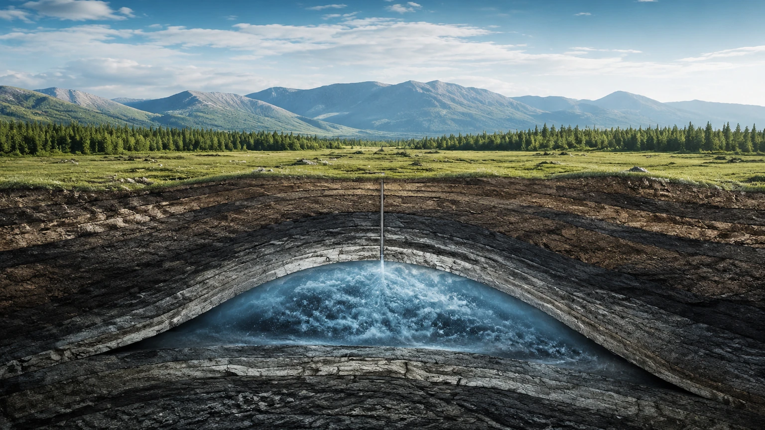
Different storage configurations—such as bulk cryogenic tanks, high-pressure cylinders, or underground geological storage buffers—require specific instrumentation. The following technologies are commonly deployed by manufacturers like Welk to meet these needs.
Radar Level Meters (80 GHz)
High-frequency radar (80 GHz) has become the industry standard for non-contact level measurement in carbon dioxide storage. The narrow beam angle allows for installation in narrow nozzles and minimizes interference from internal tank structures.
* Advantages: Non-contact, high precision (±1 mm), and unaffected by pressure or temperature fluctuations in the vapor space.
* Challenges: Liquid CO2 has a low dielectric constant ($\epsilon_r \approx 1.6$), which results in a weak reflection. Modern 80 GHz radar units are designed with high sensitivity to overcome this limitation.
Guided Wave Radar (GWR)
Guided wave radar uses a probe to direct the microwave signal to the liquid surface. This is particularly effective for CO2 because the probe concentrates the energy, making it easier to detect the low-dielectric surface of the liquid.
* Advantages: Extremely reliable in turbulent conditions or when foam is present.
* Challenges: The probe is in contact with the medium, which may require specific material compatibility (e.g., Stainless Steel 316L).
Magnetic Level Gauges
For pressurized CO2 vessels, magnetic level gauges offer a high-pressure, high-safety solution. The liquid is contained within a robust bypass chamber, and the level is displayed via magnetic flaps or a follower.
* Advantages: No risk of glass breakage (unlike traditional sight glasses) and clear visual monitoring.
* Challenges: Limited to relatively clean liquids to prevent the float from sticking.
Carbon Dioxide Storage Selection Table
Choosing the right instrument depends on the specific parameters of the storage facility. The table below summarizes the suitability of various technologies based on typical industrial CO2 storage conditions.
| Technology | Typical Application | Max Pressure (Approx.) | Accuracy | Maintenance Level |
| :— | :— | :— | :— | :— |
| 80 GHz Radar | Large Cryogenic Tanks | 40 bar+ | High (±1mm) | Low |
| Guided Wave Radar | High-Pressure Buffers | 100 bar+ | High (±2mm) | Moderate |
| Magnetic Gauge | Local Visual Monitoring | 200 bar | Moderate | Moderate |
| Hydrostatic | Simple Vented Storage | 20 bar | Variable | Moderate |
| Ultrasonic | Atmospheric CO2 Gas | 1-2 bar | Moderate | Low |
For a comprehensive overview of available technologies for industrial applications, professionals can consult the Main Page of the Welk product catalog to review product options and application support.
Installation Considerations and Best Practices
Proper installation is as critical as technology selection when dealing with carbon dioxide storage. CO2 is often stored at temperatures ranging from -20°C to -30°C (-4°F to -22°F) at pressures around 20 bar (290 psi).
Thermal Insulation and Nozzle Design
In cryogenic CO2 storage, heat ingress through the measurement nozzle can cause the liquid to boil locally, creating bubbles that interfere with radar signals. It is essential to ensure that the nozzle is properly insulated. If using Guided Wave Radar, the probe must be installed away from the tank walls to prevent false reflections caused by ice buildup on the exterior of the tank.
Pressure Rating and Sealing
Carbon dioxide is a small molecule that can permeate through certain sealing materials. For high-pressure storage, hermetic seals (such as glass-to-metal seals) are recommended for electronic transmitters to prevent gas migration into the sensor housing. All flanges and process connections must be rated for the maximum allowable working pressure (MAWP) of the vessel.
Avoiding the Triple Point
Operators must ensure that the storage conditions do not drop to the triple point of CO2 (5.1 bar at -56.6°C), where solid "dry ice" can form. Instrumentation should be capable of operating across the full range of expected process conditions without failing due to extreme cold or pressure surges.
Limitations and Operational Challenges
While modern instrumentation is highly capable, carbon dioxide storage environments present specific limitations that must be managed:
1. Low Reflectivity: As mentioned, the low dielectric constant of liquid CO2 means that a significant portion of radar energy passes through the liquid rather than reflecting. This requires sensors with a high dynamic range.
2. Condensation and Frost: In cryogenic applications, condensation on the sensor face can occur. Using radar antennas with PTFE or PEEK covers can help shed droplets, and some sensors include "air purge" connections to keep the antenna clear.
3. Density Fluctuations: For hydrostatic systems, the density of CO2 varies significantly with temperature. If the temperature is not monitored and compensated for in real-time, the level reading will drift, leading to inaccurate inventory data.
4. Vapor Space Density: At very high pressures, the density of the CO2 vapor above the liquid increases, which can slightly slow down the speed of radar waves. While usually negligible below 40 bar, it may require compensation in supercritical applications.
Frequently Asked Questions (FAQs)
Q: Can ultrasonic sensors be used for liquid carbon dioxide storage?
A: Generally, no. Ultrasonic sensors are sensitive to changes in gas density and temperature. In a pressurized CO2 tank, the vapor space composition and pressure can change, leading to significant errors in the distance calculation. Radar is a much more stable choice.
Q: What is the best way to measure CO2 in a supercritical state?
A: Supercritical CO2 (above 31.1°C and 73.8 bar) lacks a distinct phase boundary between liquid and gas. In these cases, mass-based measurement or high-pressure hydrostatic transmitters are often used instead of traditional surface-reflection technologies.
Q: How often should CO2 level meters be calibrated?
A: For inventory and fiscal billing, annual calibration is recommended. For process control, a check every 24 months is usually sufficient, provided the sensor has no moving parts (like a radar meter).
Q: Is it necessary to use a bypass chamber for CO2 storage?
A: A bypass chamber (or stilling well) is highly recommended for Guided Wave Radar or Magnetic Level Gauges. It protects the sensor from turbulence and provides a calm surface for more accurate measurement, especially during filling or discharge cycles.
Conclusion
Effective carbon dioxide storage is dependent on the integration of robust storage vessels and precise level measurement instrumentation. By understanding the principles of radar, hydrostatic, and magnetic measurement, engineers can select the system that best fits their pressure, temperature, and accuracy requirements. As the industry moves toward more sophisticated carbon capture solutions, the role of reliable monitoring becomes even more central to operational success. For further technical specifications and to explore various measurement solutions, visit the Main Page to review product options and application support.