Cdu Data Center Cooling
Cdu Data Center Cooling
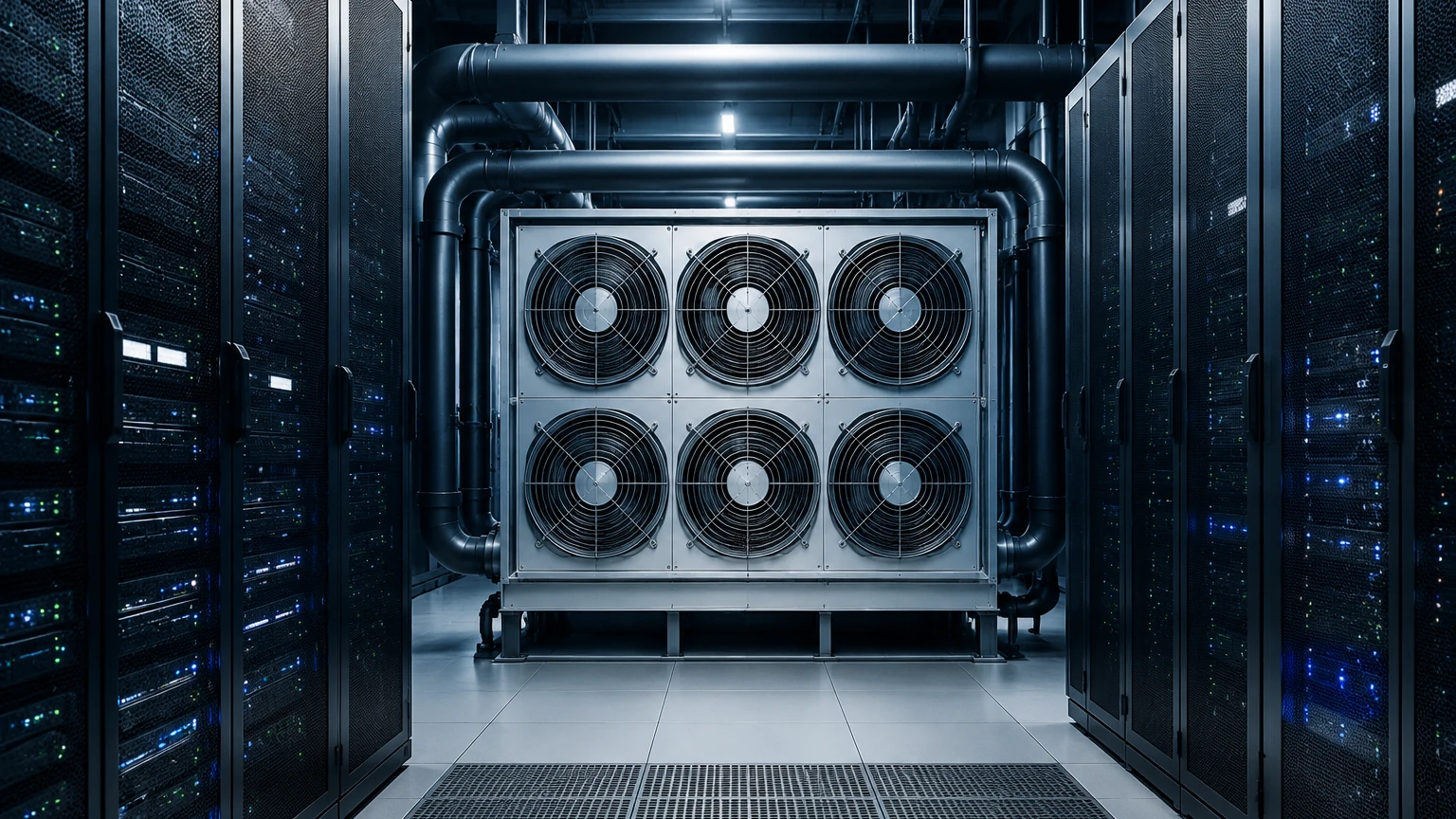
As data centers transition toward high-density computing to support Artificial Intelligence (AI) and High-Performance Computing (HPC), traditional air-cooling methods are reaching their physical limits. The Cooling Distribution Unit (CDU) has emerged as a critical component in liquid cooling architectures. In a cdu data center cooling system, the unit acts as the interface between the facility's chilled water loop and the localized liquid cooling loop that serves the server racks.
Reliable operation of a CDU depends heavily on precise instrumentation, particularly level measurement within the coolant reservoirs. Accurate monitoring ensures system pressure stability, prevents pump cavitation, and serves as a primary indicator for leak detection. This guide examines the technical requirements and measurement principles essential for managing coolant levels in modern data center environments.
The Role of the CDU in Liquid Cooling
A CDU is a specialized heat exchange system designed to manage the distribution of coolant. It performs two primary functions: heat transfer and hydraulic isolation. By separating the Facility Water Loop (FWL) from the Technology Cooling Loop (TCL), the CDU protects sensitive IT equipment from the high pressures and potentially lower water quality of the primary facility loop.
Within the TCL, the CDU maintains a specific volume of coolant—often a mixture of deionized water and corrosion inhibitors or dielectric fluids. Monitoring the level of this fluid is paramount. A drop in level typically indicates a leak within the rack or the manifold system, while an unexpected rise could suggest a failure in the heat exchanger or filling system.
Level Measurement Principles for CDU Systems
To select the appropriate sensor for cdu data center cooling applications, engineers must understand the underlying physics of different measurement technologies. Each principle offers specific advantages depending on the CDU design, reservoir size, and fluid properties.
1. Radar Level Measurement (ToF)
Radar level meters utilize Time-of-Flight (ToF) technology. The sensor emits high-frequency microwave pulses (typically in the 80 GHz range) that travel to the liquid surface and reflect back to the receiver. The distance is calculated based on the time interval between transmission and reception.
* Advantages: Non-contact measurement, unaffected by changes in fluid density, temperature, or pressure. It provides extremely high accuracy (often ±1mm to ±2mm).
* Suitability: Ideal for CDUs where high precision is required and where the coolant may have varying dielectric properties.
2. Ultrasonic Level Sensing
Ultrasonic sensors function similarly to radar but use sound waves instead of electromagnetic waves. The transducer emits an ultrasonic pulse that reflects off the liquid surface. The sensor measures the time it takes for the echo to return.
* Advantages: Cost-effective and non-contact. It is suitable for most water-based coolants.
* Limitations: Sound speed is affected by air temperature and vapor density. In enclosed CDU reservoirs where temperature fluctuations occur, temperature compensation is necessary. It also has a "dead zone" (blocking distance) near the sensor face where measurement is impossible.
3. Hydrostatic Pressure Measurement
Hydrostatic transmitters measure the pressure exerted by the liquid column at the bottom of the reservoir. The pressure (P) is proportional to the height of the liquid (h) and its density (ρ), following the formula P = ρgh.
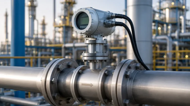
* Advantages: Simple to install and highly reliable for vented tanks. It is often used in compact CDU units where overhead space for non-contact sensors is limited.
* Limitations: Changes in fluid density (due to temperature shifts or glycol concentration changes) will affect the accuracy unless the system is calibrated for those specific variables.
4. Point Level Switches
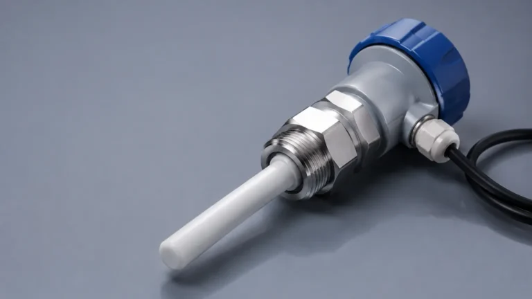
Unlike continuous transmitters, level switches provide a discrete signal when the fluid reaches a specific height. These are typically used for redundant safety systems, such as high-level alarms to prevent overflow or low-level cut-offs to protect pumps from running dry.
Technical Comparison and Selection Table
When designing a cdu data center cooling solution, selecting the right sensor involves balancing accuracy, physical footprint, and cost. The following table provides a comparison of common technologies used in industrial level measurement for CDUs.
| Technology | Accuracy | Contact Type | Ideal Application |
| :— | :— | :— | :— |
| Radar (80 GHz) | ±1 mm | Non-contact | High-precision monitoring in critical HPC environments. |
| Ultrasonic | ±0.25% of range | Non-contact | Standard liquid cooling loops with stable temperatures. |
| Hydrostatic | ±0.1% to ±0.5% | Contact | Compact reservoirs with limited vertical clearance. |
| Magnetic Float | ±5 mm | Contact | Simple visual indication and point level control. |
| Capacitance | ±1.0% | Contact | Small tanks with non-conductive dielectric fluids. |
Installation and Engineering Considerations
Integrating level sensors into a CDU requires careful attention to the mechanical and electrical environment of the data center rack.
Mounting and Turbulence
CDU reservoirs are often small and may experience turbulence due to high flow rates. When installing ultrasonic or radar sensors, ensure the beam path is clear of internal obstructions like baffles or fill pipes. If turbulence is significant, a stilling well (a vertical pipe installed inside the tank) may be required to provide a stable surface for measurement.
Fluid Compatibility
Coolants used in data centers range from treated water to specialized dielectric fluids. Ensure that the wetted materials of the sensor (such as 316L stainless steel, PTFE, or PP) are chemically compatible with the coolant to prevent corrosion or fluid contamination. For the Main Page of your instrumentation strategy, always verify the material safety data sheet (MSDS) of the coolant against the sensor specifications.
Signal Integration
Modern CDUs are usually integrated into a Data Center Infrastructure Management (DCIM) system. Level sensors should provide standard industrial outputs, such as 4-20mA (with HART), Modbus RTU, or IO-Link. This allows for real-time monitoring and automated alerts if the coolant level deviates from the setpoint.
Limitations and Potential Risks
While level measurement is a mature technology, certain factors in a cdu data center cooling environment can lead to errors:
1. Foaming: Some chemical additives in coolants can cause foaming during high-velocity circulation. Foam can absorb ultrasonic signals or cause false reflections for radar sensors. If foaming is expected, radar is generally more resilient than ultrasonic technology.
2. Condensation: In systems where the coolant temperature is significantly lower than the ambient air temperature, condensation may form on the sensor face. This can attenuate ultrasonic signals. Choosing a sensor with a specialized lens or a "drip-off" design can mitigate this.
3. Vibration: Data center racks can experience micro-vibrations from high-speed fans and pumps. Level sensors must be ruggedized and securely mounted to prevent signal noise or mechanical fatigue.
Maintenance and Calibration Guidance
To ensure the long-term reliability of the cdu data center cooling system, a regular maintenance schedule for level instrumentation should be established:
* Visual Inspection: Check for signs of leaks around sensor mounting points or cable entries.
* Cleaning: For non-contact sensors, ensure the transducer face is free of dust or crystallized coolant deposits.
* Verification: Periodically compare the sensor's electronic output against a physical reference (such as a sight glass or manual dip tape) to ensure there has been no calibration drift.
* Firmware Updates: For digital sensors (Radar/Ultrasonic), ensure the latest signal processing algorithms are applied to filter out environmental noise.
Frequently Asked Questions (FAQ)
Q: Why is level sensing more critical in liquid cooling than in air cooling?
A: In air cooling, a fan failure reduces efficiency but rarely causes immediate catastrophic damage. In liquid cooling, a loss of coolant (detected via level sensors) can lead to rapid thermal runaway of the CPU/GPU and potential water damage to the entire rack if the leak is not contained.
Q: Can I use a single level switch instead of a continuous transmitter?
A: While a level switch can prevent a pump from running dry, it cannot provide the trend data necessary for early leak detection. A continuous transmitter (like radar or hydrostatic) allows the system to detect small, slow leaks by monitoring gradual volume loss over time.
Q: What is the impact of glycol concentration on hydrostatic level sensors?
A: Glycol is denser than water. A hydrostatic sensor calibrated for pure water will over-read the level if the glycol concentration increases. It is essential to recalibrate the sensor based on the specific gravity of the final coolant mixture.
Q: How does the "dead zone" affect CDU design?
A: The dead zone (or blocking distance) is the area directly below a non-contact sensor where it cannot measure. If a CDU reservoir is very shallow, the dead zone might cover 10-20cm (approx. 4-8 inches) of the tank's height, effectively making the sensor useless for the top portion of the tank. In these cases, a hydrostatic sensor or a radar sensor with a very small dead zone is preferred.
By implementing robust level measurement technologies within the CDU, data center operators can ensure the efficiency and safety of their liquid cooling infrastructure. Selecting the right principle—whether radar, ultrasonic, or hydrostatic—requires an understanding of the specific fluid dynamics and physical constraints of the cdu data center cooling application.