Cdu for Data Center
Cdu for Data Center
As data centers transition from traditional air cooling to high-density liquid cooling architectures to support AI and high-performance computing (HPC) workloads, the Cooling Distribution Unit (CDU) has emerged as a critical infrastructure component. A CDU for data center applications acts as the primary interface between the facility’s chilled water system and the secondary cooling loop that directly services the IT equipment.
While the heat exchanger and pumps are the primary mechanical drivers of a CDU, the reliability of the system depends heavily on precise instrumentation. Specifically, level measurement within the CDU’s expansion tank or reservoir is vital for maintaining system pressure, detecting leaks, and protecting pumps from cavitation. This guide examines the technical requirements for level sensing within a CDU and provides a framework for selecting the appropriate measurement technology.
The Role of Level Measurement in CDU Systems
In a liquid cooling circuit, the CDU manages the flow, temperature, and pressure of the coolant. The secondary loop—often containing treated water or a glycol-water mixture—is a closed system. However, even closed systems require a reservoir to accommodate the thermal expansion and contraction of the fluid.
Monitoring the liquid level in this reservoir serves three primary functions:
1. Leak Detection: A sudden drop in level is often the first indicator of a breach in the secondary loop, which could potentially damage sensitive electronics.
2. Pump Protection: If the level falls below a minimum threshold, pumps may draw in air, leading to cavitation and mechanical failure.
3. Automatic Refilling: In systems with automated makeup water units, level sensors provide the trigger points for opening and closing solenoid valves to maintain the optimal volume.
Measurement Principles for CDU Reservoirs
Before selecting a specific sensor, it is essential to understand the physics behind the most common measurement principles used in data center cooling environments. Each technology interacts differently with the coolant and the compact geometry of a CDU tank.
Hydrostatic Pressure Measurement
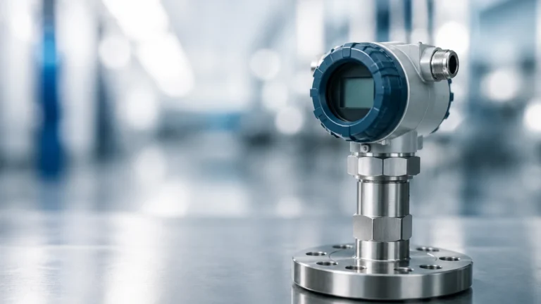
Hydrostatic level transmitters measure the pressure exerted by the liquid column above the sensor diaphragm. This pressure is directly proportional to the height of the liquid and its density.
* Principle: $P = \rho \cdot g \cdot h$, where $P$ is pressure, $\rho$ is the liquid density, $g$ is gravity, and $h$ is the height of the liquid.
* Application in CDU: These sensors are typically mounted at the bottom of the reservoir or via a side-process connection. They are highly reliable for static tanks but require compensation if the tank is pressurized or if the coolant density changes significantly with temperature fluctuations.
Ultrasonic Level Sensing
Ultrasonic sensors emit high-frequency sound waves that reflect off the surface of the liquid back to the transducer. The time-of-flight (ToF) determines the distance to the surface.
* Principle: The sensor calculates the distance based on the speed of sound. Since the speed of sound is affected by air temperature, most industrial ultrasonic sensors include integrated temperature compensation.
* Application in CDU: Being non-contact, these sensors are excellent for avoiding contamination of the coolant. However, in the confined spaces of a CDU cabinet, internal brackets or turbulence can cause false echoes if the beam angle is too wide.
Radar Level Measurement (FMCW)
Frequency Modulated Continuous Wave (FMCW) radar uses high-frequency electromagnetic pulses (typically 60 GHz or 80 GHz). Like ultrasonic sensors, radar measures time-of-flight but is unaffected by air temperature, pressure, or vapor.
* Principle: The sensor emits a continuous signal with a changing frequency. The difference between the emitted and received frequency is proportional to the distance.
* Application in CDU: Radar is increasingly favored for a CDU for data center use because it offers millimeter-level precision. Its narrow beam angle allows it to be installed in very small tanks without interference from the tank walls or internal components.
Key Evaluation Criteria for CDU Level Sensors
When specifying level instrumentation for a CDU, engineers must look beyond basic accuracy. The following criteria are specific to the data center environment:
1. Material Compatibility
Coolants used in data centers are often deionized water or specialized dielectric fluids. The sensor’s wetted parts (the parts in contact with the fluid) must be chemically compatible. Stainless steel (316L) is the standard for hydrostatic sensors, while PVDF or PTFE is preferred for the antennas of non-contact sensors to ensure no ions are leached into the cooling loop.
2. Form Factor and Mounting
CDUs are designed to fit within standard 19-inch server racks or specialized side-car cabinets. Space is at a premium. Sensors must have a low profile. For hydrostatic sensors, a small G1/2" or NPT thread is common. For radar or ultrasonic sensors, a top-mounted design that does not protrude significantly above the tank is required.
3. Signal Integration
Most CDUs are managed by a local PLC or a Rack Management Controller (RMC). The sensor must provide a signal compatible with these systems. Common outputs include:
* 4-20 mA Analog: The industry standard for continuous monitoring.
* Modbus RTU / RS485: Allows for digital transmission of multiple parameters (level and temperature) over a single pair of wires.
* IO-Link: Gaining popularity in smart data centers for remote configuration and advanced diagnostics.
Practical Selection Table
The following table compares the three primary technologies for use in a CDU for data center cooling loops.
| Feature | Hydrostatic | Ultrasonic | Radar (80 GHz) |
| :— | :— | :— | :— |
| Measurement Style | Contact (Pressure) | Non-contact (Sound) | Non-contact (EM Wave) |
| Accuracy | ±0.2% to 0.5% | ±0.25% | ±1 mm to 2 mm |
| Compactness | High (Side/Bottom mount) | Medium (Top mount) | High (Small antenna) |
| Vapor Influence | None | High (Can distort signal) | None |
| Installation Ease | Requires liquid seal | Vertical alignment critical | Very easy |
| Cost | Low to Medium | Low | Medium to High |
Installation Considerations
Proper installation is as critical as sensor selection. In a CDU, the reservoir is often subject to rapid inflow from the return line, which can create surface turbulence or foam.
* Stilling Wells: If using ultrasonic or radar sensors in a turbulent tank, a stilling well (a vertical pipe) can be used to provide a calm surface for measurement.
* Dead Zones: Every non-contact sensor has a "dead zone" or "blocking distance" directly beneath the transducer where it cannot measure. Ensure the tank’s maximum fill level does not enter this zone.
* Orientation: Hydrostatic sensors should be placed away from the direct path of the pump intake to avoid "velocity head" errors, where the movement of the fluid creates a false pressure reading.

Common Risks and Limitations
While modern sensors are highly reliable, certain risks remain inherent to CDU applications:
* Coolant Dielectric Constant: Radar sensors rely on the dielectric constant ($εr$) of the fluid to reflect the signal. While water has a high $εr$ (~80), some dielectric fluids have a very low $εr$ (<2). In these cases, a guided wave radar (GWR) or a high-sensitivity 80 GHz radar is necessary to ensure a reliable return signal.
* Condensation: In chilled water CDUs, the air space above the liquid may reach the dew point, causing condensation on the sensor face. Selecting a sensor with a specialized lens or a "dripping" antenna design prevents water droplets from clinging to the transducer and causing signal loss.
* Electromagnetic Interference (EMI): Data centers are high-EMI environments. Level sensors must be shielded and grounded correctly to prevent noise from interfering with the 4-20 mA or digital signal.
Confirming Requirements Before Procurement
Before finalizing the design of a CDU for data center deployment, project teams should confirm the following data points with their instrumentation provider:
1. Minimum and Maximum Fluid Temperature: Standard coolants operate between 15°C and 65°C, but some high-temp loops may exceed this.
2. Tank Geometry: Provide the height, width, and internal obstructions (heating elements, baffles) to the sensor manufacturer.
3. Coolant Specification: Is it PG25 (25% Propylene Glycol), DI water, or a proprietary dielectric fluid?
4. Communication Protocol: Ensure the sensor output matches the CDU’s control board (e.g., 0-10V vs 4-20mA).
For engineers seeking high-performance measurement solutions tailored to these specific industrial requirements, it is advisable to Review product options and application support to ensure the selected hardware meets the rigorous uptime demands of a modern data center.
Frequently Asked Questions (FAQs)
Q: Can I use a simple float switch instead of a continuous level sensor?
A: While a float switch is cost-effective for high/low alarms, it does not provide the granularity needed for leak detection or trend analysis. Most modern CDUs use a continuous level sensor for monitoring and a secondary float switch as a redundant safety cutoff.
Q: How often do CDU level sensors need calibration?
A: Hydrostatic sensors should be checked annually for zero-drift. Non-contact radar sensors are generally "fit and forget" and rarely require recalibration unless the physical dimensions of the tank change.
Q: Is 80 GHz radar overkill for a small CDU tank?
A: Not necessarily. The primary benefit of 80 GHz is the narrow beam (often as small as 3 degrees), which allows the sensor to ignore internal tank features that would confuse a lower-frequency radar or an ultrasonic sensor.
Conclusion
The integration of a robust CDU for data center cooling is a prerequisite for the next generation of IT infrastructure. By applying rigorous engineering standards to the selection of level measurement instruments—prioritizing accuracy, material compatibility, and signal integrity—operators can significantly reduce the risk of downtime and liquid-related hardware damage. Whether utilizing hydrostatic pressure for its simplicity or radar for its precision, the goal remains the same: total visibility into the thermal management loop.