Flow Lines
Flow Lines
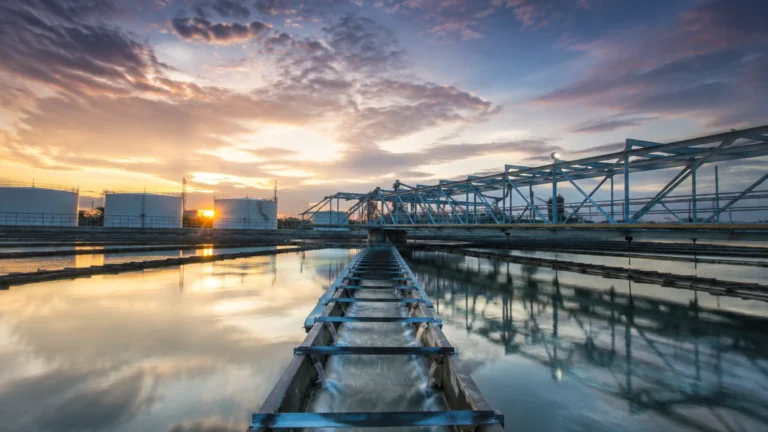
In industrial process engineering, flow lines serve as the critical conduits transporting raw fluids—liquids, gases, or multiphase mixtures—from a source to a processing or storage facility. Whether in oil and gas production, chemical manufacturing, or large-scale water treatment, the management of these lines is inextricably linked to accurate level measurement. Without precise level control at the entry and exit points of flow lines, systems risk overpressure, equipment damage, and process inefficiencies.
This guide examines the technical relationship between flow lines and level measurement instrumentation, providing engineers with the necessary criteria for selecting, installing, and maintaining sensors in these demanding environments.
The Role of Level Measurement in Flow Line Systems
Flow lines rarely operate in isolation. They typically connect wellheads to separators, storage tanks to pump stations, or reactors to downstream processing units. Level measurement instruments are required at various nodes to ensure the fluid dynamics within the flow lines remain stable.
Separator Management
In the upstream oil and gas sector, flow lines deliver a mixture of oil, water, and gas to a separator. Maintaining the liquid level within the separator is vital. If the level is too high, liquid may enter the gas outlet (carry-over); if it is too low, gas may enter the liquid outlet (carry-under). Both scenarios can cause catastrophic failure in downstream equipment.
Slug Catching
Flow lines often experience "slugging," where large pockets of liquid and gas move through the pipe at irregular intervals. Slug catchers, located at the end of long flow lines, require high-speed, reliable level measurement to manage these sudden surges and prevent the flooding of downstream facilities.
Surge Tanks and Buffering
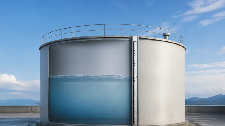
In chemical and water treatment applications, flow lines feed into surge tanks designed to buffer variations in flow rates. Level sensors in these tanks provide the feedback necessary to modulate pump speeds and valve positions, ensuring the flow lines do not exceed their design pressure or velocity limits.
Measurement Principles for Flow Line Applications
Before selecting a specific instrument, it is essential to understand the physics behind the primary technologies used in industrial level measurement. Each principle offers distinct advantages depending on the fluid properties and environmental conditions of the flow lines.
Radar Level Measurement (ToF)
Radar sensors operate on the Time-of-Flight (ToF) principle. The device emits a high-frequency electromagnetic pulse (typically in the 26 GHz or 80 GHz range) that travels to the product surface and reflects back to the sensor. The distance is calculated based on the time interval between emission and reception.
* Non-Contact Radar: Ideal for corrosive or volatile fluids found in flow lines, as the sensor does not touch the medium. It is unaffected by pressure, temperature, or vacuum conditions.
* Guided Wave Radar (GWR): Uses a probe (cable or rod) to guide the microwave pulse. This is particularly effective for low dielectric fluids or applications with heavy foam and turbulence at the flow line discharge point.
Ultrasonic Level Sensors
Ultrasonic sensors function similarly to radar but use sound waves instead of electromagnetic pulses. The sensor measures the time it takes for an ultrasonic pulse to travel to the surface and back. While cost-effective, these are generally limited to atmospheric or low-pressure applications and can be influenced by air temperature gradients, heavy vapors, or dust.
Hydrostatic Level Transmitters
This principle relies on the relationship between liquid height and the pressure exerted at the bottom of a vessel. The formula $P = \rho \cdot g \cdot h$ (where $P$ is pressure, $\rho$ is density, $g$ is gravity, and $h$ is height) allows the sensor to determine the level. For flow lines connected to pressurized tanks, a differential pressure (DP) transmitter is used to compensate for the headspace pressure.
Magnetic Level Gauges (MLG)
MLGs utilize a float containing a high-intensity magnet. As the liquid level in a bypass chamber (connected to the main vessel) rises and falls, the float moves accordingly. This movement flips magnetic flags on an external scale, providing a visual indication. These are often paired with reed switches or transmitters for remote monitoring in hazardous areas.
Selection Criteria for Flow Line Level Instruments
Selecting the right instrument requires a detailed analysis of the process conditions. Engineers should consult the Main Page of technical documentation to review specific product tolerances before final selection.
| Criteria | Radar (Non-Contact) | Guided Wave Radar | Hydrostatic | Magnetic Level Gauge |
| :— | :— | :— | :— | :— |
| Fluid Type | Liquids/Solids | Liquids/Slurries | Clean Liquids | Clean/Corrosive Liquids |
| Pressure Range | Up to 160 bar | Up to 400 bar | Up to 1000 bar | Up to 250 bar |
| Temp. Range | -40°C to +450°C | -196°C to +450°C | -40°C to +125°C | -196°C to +400°C |
| Accuracy | ±2 mm | ±2 mm | ±0.1% of span | ±5 mm (visual) |
| Effect of Density | None | None | High | High |
| Installation | Top-mounted | Top-mounted | Bottom/Side | Side-mounted (Bypass) |
Installation Considerations and Best Practices
Proper installation is as critical as the choice of technology. When flow lines discharge into a vessel, the resulting turbulence can interfere with level readings.
1. Nozzle Positioning: Level sensors should be installed away from the flow line inlet nozzle to avoid "false echoes" from falling liquid or interference from surface agitation.
2. Stilling Wells and Bypass Chambers: For high-turbulence applications, installing the sensor within a stilling well (a vertical pipe inside the tank) or a bypass chamber (external to the tank) provides a calm surface for measurement. This is standard practice for flow lines carrying high-velocity fluids.
3. Beam Angle: For non-contact radar, ensure the beam angle does not intersect with the tank walls, ladders, or the incoming stream from the flow lines. Modern 80 GHz radars offer narrower beam angles, which simplify installation in narrow vessels.
4. Pressure Equalization: In hydrostatic systems, ensure that the sensing diaphragm is protected from the direct kinetic energy of the fluid entering from the flow lines, which can cause "pressure spikes" and erratic readings.

Common Risks and Limitations
Engineers must account for several operational risks when designing level systems for flow lines:
* Paraffin and Scaling: In oil flow lines, paraffin wax or mineral scale can build up on GWR probes or within bypass chambers. This can cause the float in an MLG to stick or the radar signal to attenuate. Regular maintenance or the use of non-contact radar is recommended in these scenarios.
* Foaming: High-velocity flow lines often create foam upon entering a vessel. Ultrasonic sensors may fail entirely in these conditions, while non-contact radar may provide inconsistent readings. GWR is typically the most robust solution for heavy foam.
* Slugging and Surges: Rapid changes in level due to flow line slugging can overwhelm sensors with slow dampening or update rates. High-speed electronic transmitters are required to provide real-time data for emergency shutdown systems (ESD).
* Ambient Conditions: Flow lines in extreme climates (e.g., Arctic or Desert) require instrumentation with appropriate ingress protection (IP67/68) and temperature compensation to prevent electronic drift.
Frequently Asked Questions (FAQs)
Q: How do I measure the level in a flow line that is only partially full?
A: For horizontal flow lines that are not always full, area-velocity flow meters or specialized non-contact radar sensors designed for open channels/pipes are used. Standard tank level sensors are generally not suitable for direct pipe mounting unless a vertical "T" section is installed.
Q: Can I use one sensor for different fluids in the same flow line?
A: If the fluids have different dielectrics, radar (specifically GWR) can often detect the interface between them (e.g., oil and water). However, hydrostatic sensors will require recalibration if the fluid density changes significantly.
Q: What is the maximum distance a level sensor can be from the flow line discharge?
A: There is no fixed distance, but the sensor should be placed in a zone where the surface is representative of the total volume. Placing it too close to the discharge causes noise; placing it too far may result in a lag in detecting surges from the flow lines.
Conclusion
Flow lines are the lifeblood of industrial processes, and their efficient operation depends on the precision of the level measurement instruments at their terminals. By understanding the measurement principles—from the versatility of radar to the mechanical reliability of magnetic gauges—engineers can mitigate risks such as slugging, foam, and scaling.
When designing your system, always prioritize technologies that match the specific dielectric, density, and pressure profiles of your process. For detailed technical specifications and to explore the full range of industrial measurement solutions, visit the Welk Main Page to find the optimal fit for your flow line infrastructure.