Clamp on Type Ultrasonic Flow Meter
Clamp on Type Ultrasonic Flow Meter
In the landscape of industrial process control, the ability to measure fluid flow without interrupting operations or compromising the integrity of piping systems is a significant advantage. The clamp on type ultrasonic flow meter has emerged as a primary solution for these requirements. By utilizing ultrasonic transducers mounted to the exterior of a pipe, these instruments provide accurate flow data for a wide range of liquids, from ultrapure water to corrosive chemicals. As a professional manufacturer of industrial measurement instruments, Welk integrates these technologies into broader automation strategies, ensuring that facilities can maintain high efficiency. For a comprehensive overview of available instrumentation, engineers often refer to the Main Page of specialized equipment providers.
Understanding the Measurement Principles
The operation of a clamp on type ultrasonic flow meter is based on the physics of sound propagation in a moving fluid. There are two primary technologies used in these devices: Transit-Time and Doppler Effect. Understanding which principle a specific meter employs is critical for correct application.
Transit-Time Method
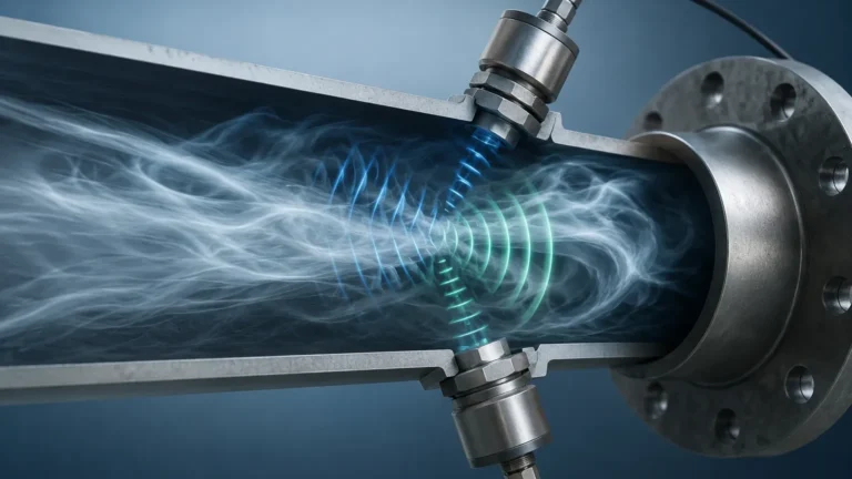
This is the most common method for clean liquids. It utilizes a pair of transducers (A and B) that function as both transmitters and receivers. Transducer A sends an ultrasonic signal to Transducer B (downstream), and Transducer B sends a signal back to Transducer A (upstream).
When the fluid is moving, the signal traveling downstream moves faster than the signal traveling upstream. The meter measures this time difference ($Δt$). The flow velocity ($V$) is proportional to this time difference, calculated using the formula:
$$V = K · Δt$$
Where $K$ is a calibration constant determined by the pipe geometry and fluid properties. Once the velocity is known, the volumetric flow rate is calculated by multiplying the velocity by the cross-sectional area of the pipe.
Doppler Effect Method
This principle is used for liquids containing suspended solids or entrained gas bubbles. The transducers transmit a continuous ultrasonic beam into the fluid. These sound waves reflect off the particles or bubbles moving with the flow. Because the reflectors are moving, the frequency of the reflected signal is shifted (the Doppler shift). The frequency shift is directly proportional to the flow velocity. While generally less accurate than transit-time meters for clean liquids, Doppler meters are essential for slurries and aerated fluids where transit-time signals would be attenuated.
Advantages of Non-Invasive Flow Measurement
The "clamp-on" design offers several distinct benefits over inline flow meters like electromagnetic or turbine meters:
1. No Process Downtime: Installation does not require cutting pipes or shutting down the process. This is particularly valuable in 24/7 manufacturing environments or municipal water systems.
2. Zero Pressure Drop: Since there are no internal components or obstructions within the pipe, the meter introduces no hydraulic resistance, leading to energy savings in pumping systems.
3. Chemical Compatibility: Because the sensors never touch the fluid, there is no risk of corrosion or contamination. This makes them ideal for measuring aggressive acids, caustic solutions, or high-purity liquids in the pharmaceutical industry.
4. Portability: Many clamp on type ultrasonic flow meter models are designed for temporary audits, allowing engineers to verify the performance of existing inline meters or balance complex HVAC systems.
5. High Pressure and Temperature Safety: Since the pipe wall remains intact, there are no leak paths or pressure rating concerns associated with the meter body itself.
Key Selection Criteria for Industrial Applications
Selecting the right clamp on type ultrasonic flow meter requires a detailed analysis of the application environment. Engineers should evaluate the following parameters before procurement:
Pipe Material and Condition
Ultrasonic signals must pass through the pipe wall. Materials like carbon steel, stainless steel, PVC, and ductile iron are generally excellent conductors of ultrasound. However, pipes with internal liners (like cement, rubber, or bitumen) can be challenging if the liner is not perfectly bonded to the host pipe. Air gaps between the liner and the wall will block the ultrasonic signal entirely.
Fluid Properties
The fluid must be sonically conductive. For transit-time meters, the concentration of solids or bubbles should typically be less than 2% to 5% by volume. High viscosity fluids can also affect the flow profile, requiring the meter to have advanced Reynolds number compensation algorithms.
Flow Profile and Straight Pipe Runs
Like most flow measurement technologies, ultrasonic meters require a fully developed flow profile to achieve specified accuracy. Standard guidelines suggest a minimum of 10 diameters (10D) of straight pipe upstream and 5 diameters (5D) downstream from the sensor location. If valves, pumps, or elbows are present, longer straight runs may be required.
Practical Installation Guidelines and Mounting Methods
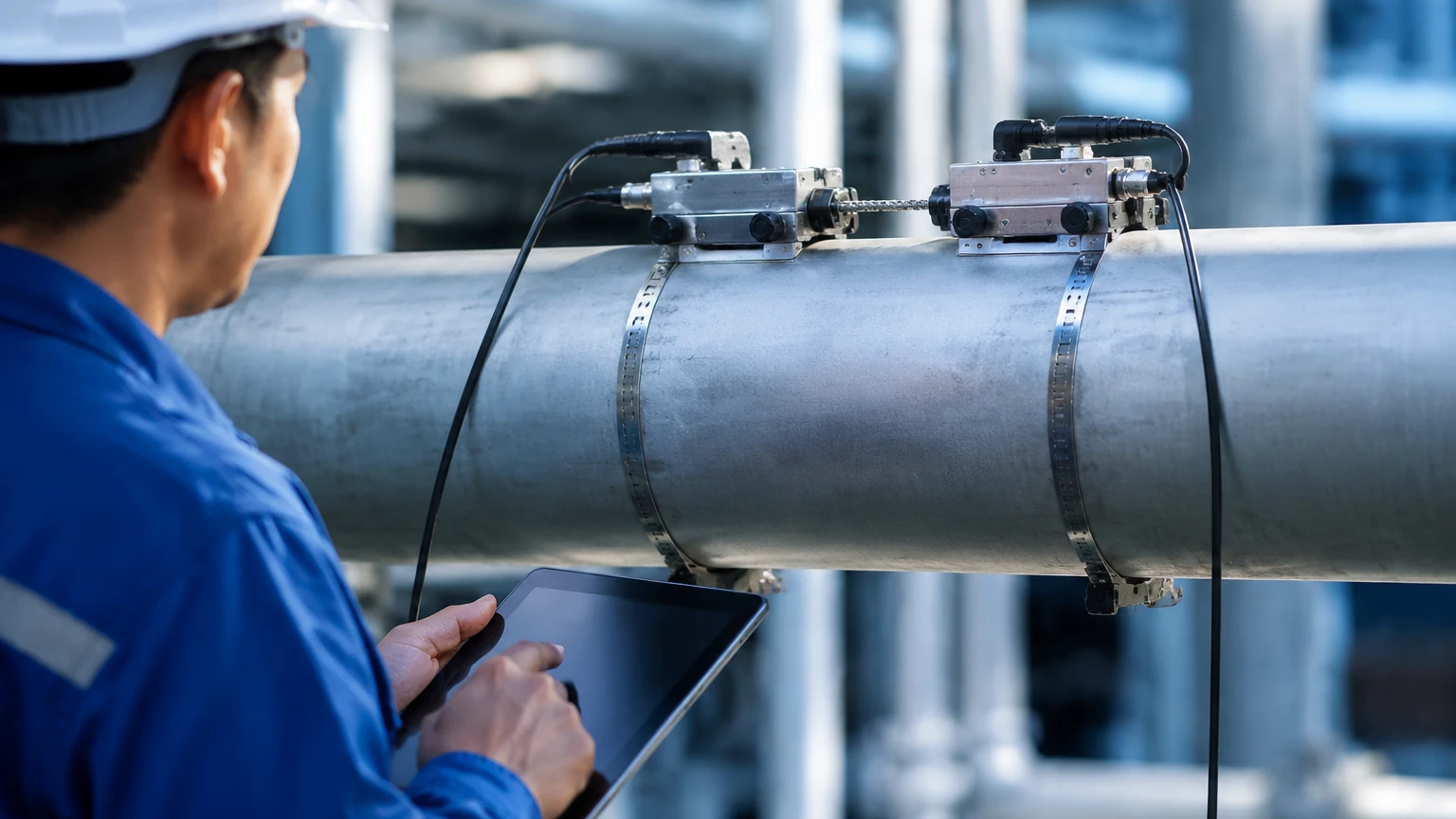
The accuracy of a clamp on type ultrasonic flow meter is heavily dependent on the quality of the installation. There are three primary mounting configurations used depending on the pipe size and fluid characteristics:
* V-Method: The most common configuration for pipe diameters ranging from 25 mm to 400 mm. The transducers are installed on the same side of the pipe, and the signal reflects off the opposite wall. This doubles the path length, increasing the time resolution and accuracy.
* Z-Method: Used for larger pipes (typically above 400 mm) or in cases where the fluid is highly attenuative. The transducers are mounted on opposite sides of the pipe, and the signal crosses the pipe only once.
* W-Method: Used for very small pipes (usually under 50 mm). The signal reflects three times, effectively quadrupling the path length to measure very low flow velocities.
Surface Preparation
The pipe surface must be cleaned of rust, loose paint, and scale. A smooth, flat surface is required for the transducers to make full contact. A coupling agent (ultrasonic grease or gel) is applied between the transducer face and the pipe to eliminate air gaps and facilitate signal transmission.
Technical Comparison and Selection Table
The following table provides a general reference for evaluating the suitability of different ultrasonic technologies based on application requirements.
| Feature | Transit-Time (Clamp-On) | Doppler (Clamp-On) |
| :— | :— | :— |
| Primary Fluid Type | Clean liquids, water, oils | Slurries, wastewater, aerated liquids |
| Suspended Solids | < 2% (typical) | > 100 ppm (required) |
| Accuracy (Typical) | ±0.5% to ±2.0% of rate | ±2.0% to ±5.0% of FS |
| Pipe Size Range | 15 mm to 6000 mm | 25 mm to 6000 mm |
| Installation Effort | Moderate (requires precise spacing) | Low (spacing is less critical) |
| Sensitivity to Profile | High | Moderate |
Limitations and Operational Risks
While highly versatile, the clamp on type ultrasonic flow meter is not a universal solution. Users should be aware of the following limitations:
* Signal Attenuation: Highly aerated liquids or fluids with high concentrations of large particles can scatter the ultrasonic signal, leading to a "Signal Lost" error in transit-time meters.
* Pipe Wall Thickness Errors: The meter calculates the internal diameter (ID) based on the user-entered outer diameter (OD) and wall thickness. An error in measuring the wall thickness or the presence of internal scale (which reduces the ID) will lead to a direct volumetric flow error.
* Temperature Limits: Standard transducers are often limited to 80°C or 120°C. High-temperature applications require specialized transducers and high-temperature couplants to prevent sensor damage.
* Ambient Noise: In some heavy industrial environments, high-frequency mechanical vibration from nearby pumps or machinery can interfere with the ultrasonic signal, though modern digital signal processing (DSP) has mitigated much of this risk.
Frequently Asked Questions (FAQs)
Q: Can a clamp on type ultrasonic flow meter measure flow in partially filled pipes?
A: Generally, no. Most ultrasonic flow meters require the pipe to be completely full to accurately calculate the cross-sectional area and ensure the ultrasonic signal passes through the fluid. For partially filled pipes, specialized area-velocity meters are required.
Q: How often does the coupling grease need to be reapplied?
A: For permanent installations, high-quality silicone-based couplants or solid coupling pads can last for several years. However, in outdoor environments with extreme temperature cycling, it is recommended to inspect the signal strength annually and reapply couplant if the signal quality has degraded.
Q: Can these meters measure gas flow?
A: While there are specialized clamp-on meters for high-pressure gas, the standard clamp on type ultrasonic flow meter used in industrial automation is designed for liquids. Gas has a much lower acoustic impedance, making it significantly harder for ultrasound to transition from the pipe wall into the gas.
Q: What is the minimum flow velocity these meters can detect?
A: Most modern meters can detect velocities as low as 0.01 m/s, though accuracy typically improves once the velocity exceeds 0.1 m/s. This makes them excellent for detecting leaks in large distribution networks.
For engineers looking to integrate flow data with level measurement systems, such as those used in chemical tank farms or water treatment plants, selecting a reliable manufacturer is paramount. Welk provides a range of solutions that complement flow monitoring, including radar and ultrasonic level sensors. To explore the full catalog of industrial measurement technologies, visit the Main Page for detailed product specifications and application support.