Flow Indicating Transmitter
Flow Indicating Transmitter
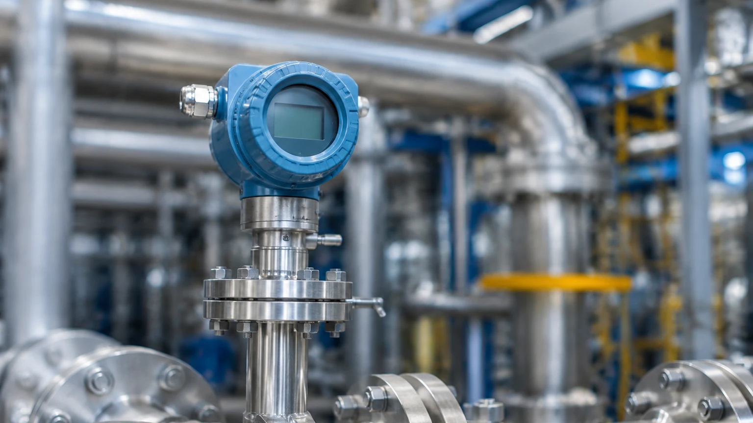
In the landscape of industrial process control, the ability to monitor and transmit fluid dynamics data in real-time is fundamental to operational efficiency and safety. A flow indicating transmitter (FIT) serves as a dual-purpose instrument, providing both a local visual readout of the flow rate and an electronic signal transmitted to a centralized control system, such as a Programmable Logic Controller (PLC) or Distributed Control System (DCS). Unlike a simple flow meter, which may only offer a local mechanical display, or a basic transmitter that lacks a field-viewable interface, the flow indicating transmitter bridges the gap between field-level manual monitoring and high-level automated control.
For engineers and plant managers, selecting the correct FIT involves understanding the underlying physics of the fluid, the mechanical constraints of the piping system, and the electronic requirements of the facility's automation architecture. This guide explores the principles, selection criteria, and installation best practices for these essential industrial components.
Measurement Principles and Technologies
Before selecting a flow indicating transmitter, it is necessary to understand the diverse physical principles used to derive flow data. No single technology is universal; the choice depends heavily on the fluid's state (liquid, gas, or steam), conductivity, viscosity, and cleanliness.
1. Electromagnetic Flow Transmitters (Magmeters)
Electromagnetic transmitters operate based on Faraday’s Law of Induction. When a conductive fluid moves through a magnetic field generated by the transmitter’s coils, it produces a voltage proportional to its velocity.
* Application: Best for conductive liquids, slurries, and water treatment.
* Advantage: No moving parts and zero pressure drop.
* Limitation: Cannot measure non-conductive fluids like oils or deionized water.
2. Ultrasonic Flow Transmitters
These instruments typically use "Transit Time" or "Doppler" technology. Transit time transmitters send ultrasonic pulses upstream and downstream; the difference in travel time is proportional to the flow velocity. Doppler transmitters reflect sound off particles or bubbles in the fluid.
* Application: Chemical processing and large-diameter water pipes.
* Advantage: Often available in "clamp-on" designs that do not require cutting the pipe.
* Limitation: Transit time requires clean fluids, while Doppler requires at least 100 microns of particles or bubbles.
3. Vortex Shedding Transmitters
Based on the Von Kármán effect, these transmitters place a "bluff body" in the flow stream. As fluid passes this body, vortices are shed alternately on each side. The frequency of these vortices is directly proportional to the flow velocity.
* Application: High-temperature steam, gases, and low-viscosity liquids.
* Advantage: Highly reliable in high-temperature environments up to 400°C (752°F).
* Limitation: Requires a minimum Reynolds number to function accurately.
4. Differential Pressure (DP) Transmitters
DP transmitters measure the pressure drop across a restriction in the pipe, such as an orifice plate, Venturi tube, or flow nozzle. According to Bernoulli’s principle, the square root of the pressure drop is proportional to the flow rate.
* Application: Versatile for gas, liquid, and steam.
* Advantage: Well-understood technology with standardized calculation methods.
* Limitation: Causes a permanent pressure loss in the system and requires impulse piping which can clog.
The Role of the "Indicating" Component
The "indicating" portion of a flow indicating transmitter is usually a digital LCD or an analog dial integrated into the transmitter housing. In modern B2B environments, the digital display provides more than just the current flow rate (e.g., L/min or m³/h). It often displays:
* Totalized Flow: The cumulative volume that has passed through the meter.
* Diagnostic Codes: Real-time alerts regarding sensor health, empty pipe detection, or signal interference.
* Output Status: The current mA output being sent to the control room.
This local interface is critical during commissioning and maintenance. It allows field technicians to verify that the remote SCADA readings match the actual field conditions without needing to communicate back and forth with the control room via radio.
Key Evaluation and Selection Criteria
Choosing a flow indicating transmitter requires a systematic evaluation of the process environment. Engineers should use the following criteria to narrow down their options:
Fluid Properties
* Phase: Is the medium a liquid, gas, or steam?
* Conductivity: For electromagnetic meters, a minimum conductivity (usually >5 μS/cm) is required.
* Viscosity: High-viscosity fluids may require positive displacement or mass flow meters rather than vortex or turbine types.
* Corrosiveness: The wetted parts (liners and electrodes) must be compatible with the chemical makeup of the fluid.
Process Conditions
* Pressure: Ensure the transmitter housing and flange ratings exceed the maximum system pressure (e.g., PN16, PN40, or ANSI 150/300).
* Temperature: Electronic components in the transmitter head may need to be remote-mounted if the process temperature exceeds 150°C (302°F).
* Flow Range (Turndown Ratio): The ratio between the maximum and minimum flow the meter can accurately measure. A 10:1 ratio is standard, but some ultrasonic meters offer 100:1.
Practical Selection Table
| Technology | Typical Accuracy | Fluid Type | Pressure Drop | Ideal For |
| :— | :— | :— | :— | :— |
| Electromagnetic | ±0.5% | Conductive Liquids | None | Water, Acids, Slurries |
| Ultrasonic | ±1.0% | Clean/Dirty Liquids | None | Large Pipes, Retrofits |
| Vortex | ±1.0% | Steam, Gas, Liquid | Moderate | Steam Boiler Outlets |
| Differential Pressure | ±1.0% – 2.0% | All Fluids | High | High-Pressure Gas |
| Thermal Mass | ±1.0% | Gases | Low | Compressed Air, Nitrogen |
Installation Considerations
Even the most expensive flow indicating transmitter will fail to provide accurate data if installed incorrectly. Most measurement errors in industrial settings stem from poor installation rather than instrument failure.
Straight Pipe Requirements
Flow meters generally require a "fully developed flow profile" to measure accurately. Turbulence caused by elbows, valves, or pumps can skew readings.
* Upstream: Usually requires 10 to 20 diameters (D) of straight pipe.
* Downstream: Usually requires 3 to 5 diameters (D) of straight pipe.
* *Example:* For a 100 mm (4-inch) pipe, you may need 1 meter of straight pipe before the transmitter.
Orientation and Mounting
* Liquid Service: The pipe must always be full. Install the transmitter in a low point or a vertical upward-flow section to prevent air pockets.
* Gas Service: Install the transmitter in a high point to prevent moisture/condensate from pooling in the sensor.
* Grounding: For electromagnetic transmitters, proper grounding to the fluid is mandatory to eliminate stray electrical noise that could interfere with the low-voltage signal.
Signal Transmission
Most FITs use a 4-20 mA DC signal, often with HART (Highway Addressable Remote Transducer) protocol overlaid. This allows for digital communication over the same two wires used for the analog signal. In newer facilities, Modbus RS485 or Foundation Fieldbus may be preferred for multi-variable data transmission.
Common Risks and Limitations
When deploying a flow indicating transmitter, be aware of these common industrial pitfalls:
1. Cavitation: In liquid applications, if the pressure drops too low at the meter's restriction point, vapor bubbles form and collapse. This damages the instrument and causes massive measurement errors.
2. Entrained Air: In ultrasonic or electromagnetic meters, air bubbles can attenuate the signal or cause the meter to read "empty pipe," halting the process.
3. Scaling and Coating: In chemical or wastewater applications, material can build up on the electrodes or the inner wall of the meter. This changes the internal diameter or insulates the electrodes, leading to a gradual drift in accuracy.
4. Vibration: Vortex and some DP transmitters are sensitive to pipe vibration. If the installation site is near a heavy pump or compressor, specialized damping or remote mounting may be necessary.
Frequently Asked Questions (FAQs)
Q: Can a flow indicating transmitter measure mass flow?
A: Most FITs measure volumetric flow (volume per unit time). To calculate mass flow, you must either use a Coriolis meter or combine the volumetric data with temperature and pressure compensation (common in steam and gas applications).
Q: How often should a transmitter be calibrated?
A: This depends on the industry and the criticality of the measurement. In regulated industries like pharmaceuticals or food production, annual calibration is standard. In general water service, a check every 2-3 years may suffice.
Q: What is the difference between a 2-wire and a 4-wire transmitter?
A: A 2-wire transmitter draws its power from the 4-20 mA current loop itself. A 4-wire transmitter has two wires for power (usually 24V DC or 110/220V AC) and two separate wires for the signal. 4-wire systems are typically used when the instrument requires more power, such as for heated sensors or heavy-duty backlighting.
Q: Can I use one transmitter for multiple fluid types?
A: Generally, no. Most transmitters are calibrated for a specific fluid density and viscosity. While some digital transmitters allow you to change fluid profiles in the menu, the physical sensor (e.g., the liner of a magmeter) must still be chemically compatible with all fluids used.
Summary and Next Steps
A flow indicating transmitter is a vital link in the chain of industrial automation. By providing both a local visual reference and a standardized electronic output, it ensures that field operators and control room engineers are working with the same accurate data. When selecting a unit, prioritize fluid compatibility and installation environment over the lowest initial cost, as the total cost of ownership is heavily influenced by maintenance and downtime.
As a professional manufacturer of industrial measurement instruments, Welk provides high-performance solutions across various sectors, including water treatment, chemical processing, and oil and gas. For detailed technical specifications, customized OEM/ODM services, or to explore our full range of radar, ultrasonic, and hydrostatic measurement technologies, please visit our Main Page. Ensuring your project has the right instrumentation from the start is the most effective way to guarantee long-term operational reliability.