Clamp on Ultrasonic Flow Meter Emerson
Clamp on Ultrasonic Flow Meter Emerson
Non-invasive flow measurement technology has become a critical component in industrial process control, particularly in applications where process interruption is not feasible. Among the leading solutions in this category is the clamp on ultrasonic flow meter Emerson (often associated with the Rosemount brand), which utilizes acoustic wave propagation to determine liquid velocity without contacting the medium. This guide provides a technical overview of the measurement principles, selection criteria, and installation requirements for these instruments within a broader industrial measurement framework.
Measurement Principles of Ultrasonic Technology
To understand the performance of a clamp on ultrasonic flow meter Emerson, it is essential to first master the underlying physics of ultrasonic measurement. There are two primary methods used in industrial ultrasonic instrumentation: transit-time and Doppler effect.
Transit-Time Method
Transit-time ultrasonic flow meters are the most common type used for clean liquids. This method relies on the principle that an acoustic signal traveling with the flow of a liquid moves faster than a signal traveling against the flow.
The instrument utilizes two transducers, typically mounted on the exterior of the pipe. These transducers act as both transmitters and receivers. The time difference (Δt) between the upstream and downstream signals is directly proportional to the velocity of the liquid. The formula for velocity ($v$) can be expressed as:
$$v = \frac{K \cdot \Delta t}{t_{up} \cdot t_{down}}$$
Where $K$ is a calibration factor based on pipe geometry and $t$ represents the travel times. Once the velocity is determined and the cross-sectional area of the pipe is known, the volumetric flow rate is calculated. This technology requires a relatively clean fluid to ensure the acoustic signal is not scattered or absorbed.
Doppler Effect Method
In contrast to transit-time, the Doppler effect method is used for liquids containing suspended solids or entrained air bubbles. The transducers transmit a signal at a known frequency. When this signal encounters moving particles or bubbles, it reflects back to the receiver with a frequency shift. This shift (the Doppler frequency) is proportional to the flow velocity. While Emerson's primary clamp-on offerings often focus on high-precision transit-time technology, understanding both methods is vital for correct instrument selection.
Key Evaluation Criteria for Emerson Clamp-on Solutions
When evaluating a clamp on ultrasonic flow meter Emerson, engineers must consider several technical parameters to ensure the device meets the specific needs of the application. Unlike wetted sensors, clamp-on meters are highly dependent on the pipe's physical characteristics.
Pipe Material and Condition
The acoustic signal must pass through the pipe wall, the liquid, and back through the pipe wall. Therefore, the pipe material (e.g., carbon steel, stainless steel, PVC, or ductile iron) must be sonically conductive. Internal liners, such as cement or thick rubber, can significantly attenuate the signal, sometimes rendering clamp-on measurement impossible. It is critical to verify the pipe's wall thickness and the presence of any internal scaling.
Fluid Properties
While transit-time meters are designed for clean liquids, they can often tolerate a small percentage of solids or bubbles (typically less than 2% to 5% by volume). If the fluid is highly viscous or contains high concentrations of particulates, the signal may be lost. For complex fluid profiles, consulting a Main Page for integrated measurement solutions can provide clarity on whether ultrasonic technology or an alternative, such as hydrostatic or radar measurement, is more appropriate for the broader system.
Accuracy and Repeatability
Emerson's clamp-on meters are engineered for high repeatability, often within 0.1% to 0.3%. However, absolute accuracy is dependent on the precision of the user-entered pipe data (diameter and wall thickness). A 1 mm error in wall thickness measurement on a small pipe can lead to a significant percentage error in the calculated flow rate.
Practical Selection Table for Industrial Applications
The following table outlines typical selection parameters for clamp-on ultrasonic meters in various industrial contexts.
| Parameter | Transit-Time (Standard) | High-Temperature Options | Dirty Liquid / Slurry |
| :— | :— | :— | :— |
| Pipe Size Range | 15 mm to 6000 mm | 25 mm to 1000 mm | 25 mm to 3000 mm |
| Fluid Temperature | -40°C to 120°C | Up to 250°C | -40°C to 150°C |
| Accuracy | ±0.5% to ±2.0% of rate | ±1.0% to ±3.0% of rate | ±2.0% to ±5.0% of rate |
| Common Applications | Potable water, Glycol, Oil | Steam condensate, Hot oil | Wastewater, Pulp stock |
| Installation Type | External Clamp-on | External with Heat Heat-sinks | External Clamp-on |
Installation Considerations and Best Practices
The performance of a clamp on ultrasonic flow meter Emerson is largely determined by the quality of the installation. Because the sensors are not in direct contact with the fluid, the interface between the transducer and the pipe is the most common point of failure.
Surface Preparation
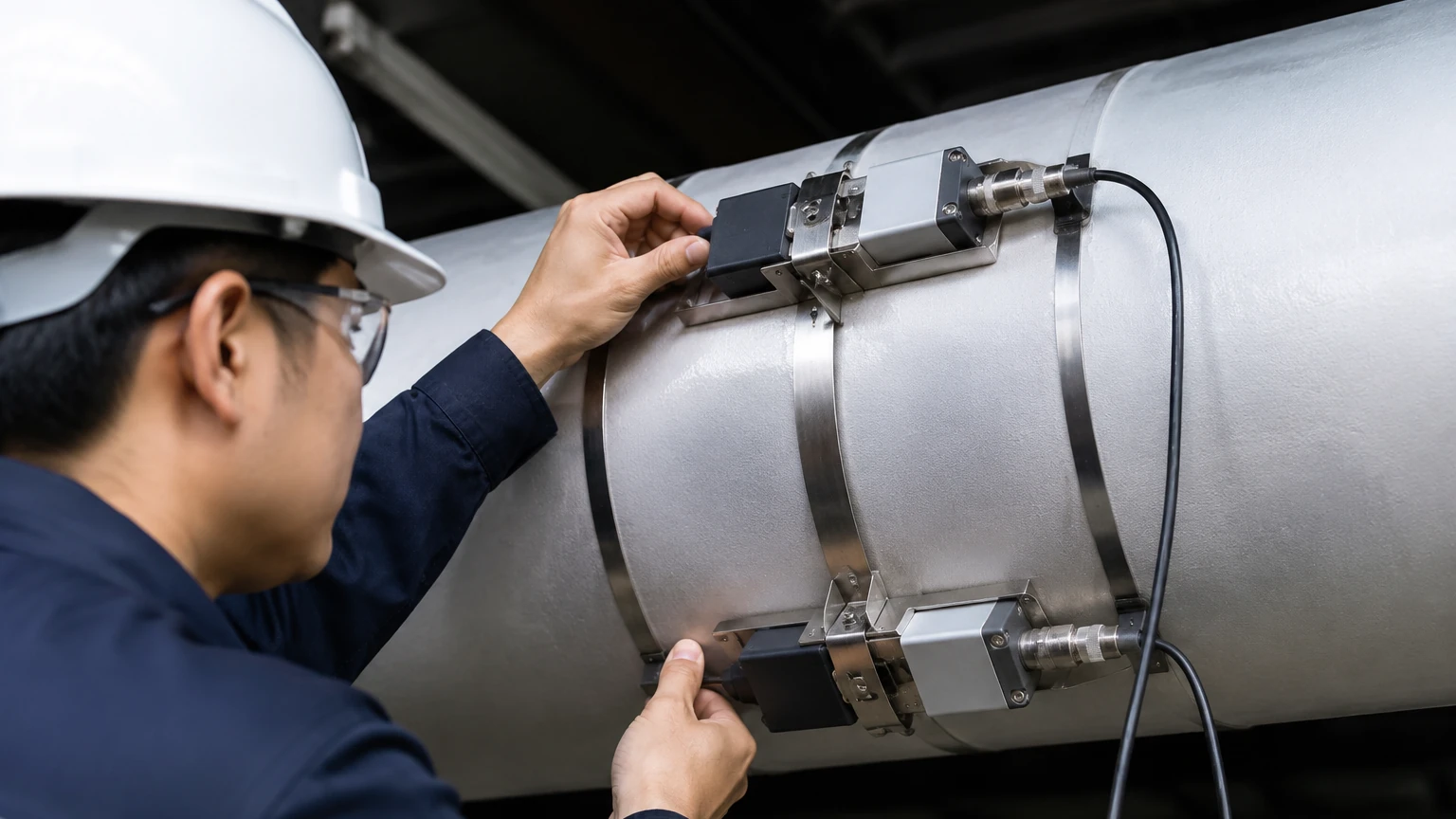
The pipe surface must be cleaned of rust, loose paint, and debris. In many cases, the surface should be ground down to bare metal to ensure optimal acoustic coupling. A coupling compound (grease or epoxy) is applied between the transducer face and the pipe to eliminate air gaps, which would otherwise block the high-frequency sound waves.
Transducer Mounting Orientations
There are three primary mounting configurations:
1. V-Mount: The signal bounces off the opposite pipe wall once. This is the standard for medium-sized pipes (50 mm to 400 mm).
2. Z-Mount: The transducers are placed on opposite sides of the pipe. The signal crosses the pipe once. This is used for large pipes or where the fluid is highly attenuative.
3. W-Mount: The signal bounces three times. This is used for very small pipes (under 50 mm) to increase the transit time and improve resolution.
Straight Pipe Requirements
To ensure a stable flow profile, the meter should be installed on a straight section of pipe. The general rule is 10 diameters (10D) of straight pipe upstream and 5 diameters (5D) downstream from any elbows, valves, or pumps. If these conditions cannot be met, the accuracy of the meter will likely degrade.
Limitations and Common Risks
While clamp-on technology offers significant advantages, including zero pressure drop and no risk of leakage, it is not a "one-size-fits-all" solution. Engineers should be aware of the following risks:
* Acoustic Short Circuiting: In some thin-walled metal pipes, the acoustic signal may travel through the pipe wall faster than through the liquid, leading to false readings.
* Entrained Air: Even small amounts of air can scatter ultrasonic signals. In horizontal pipes, transducers should be mounted at the 3 o'clock and 9 o'clock positions to avoid air pockets at the top and sediment at the bottom.
* Coupling Degradation: Over time, coupling grease can dry out or wash away, especially in outdoor or high-temperature environments. Permanent installations may require solid couplants or periodic maintenance.
Integration with Level Measurement Systems
In many industrial automation scenarios, flow measurement is only one part of the equation. For instance, in chemical dosing or water treatment, monitoring the level of the source tank is as important as monitoring the flow rate in the discharge line.
Welk, as a professional manufacturer, provides a range of level measurement instruments—including radar and ultrasonic level sensors—that complement the data provided by flow meters. While a clamp on ultrasonic flow meter Emerson measures the movement of the liquid, ultrasonic level sensors measure the distance to the liquid surface. Both technologies rely on the same fundamental principles of acoustic wave propagation, though level sensors typically operate through the air (time-of-flight) rather than through the pipe wall and liquid medium. Integrating these data points allows for mass balance calculations and more robust process safety.
Frequently Asked Questions (FAQ)
Q: Can a clamp-on flow meter measure gas flow?
A: While most Emerson clamp-on meters are designed for liquids, specialized high-power ultrasonic meters do exist for gas applications. However, gas has much lower acoustic impedance than liquids, making the measurement significantly more challenging.
Q: How do I verify the accuracy of a clamp-on meter after installation?
A: Verification is typically done using a master meter or by performing a draw-down test in a tank of known volume. Many Emerson units also feature internal diagnostics that monitor signal strength and signal-to-noise ratios to indicate health.
Q: Does pipe insulation need to be removed?
A: Yes, the insulation must be removed at the point of contact so the transducers can be mounted directly to the pipe surface. The area can be re-insulated after installation, provided the transducers are rated for the temperature.
Q: What is the impact of pipe liners on measurement?
A: Liners that are well-bonded to the pipe wall (like epoxy) generally allow the signal to pass. However, liners with an air gap between the liner and the pipe wall (common in some older plastic-lined steel pipes) will completely block the ultrasonic signal.
By following these engineering guidelines and understanding the technical boundaries of ultrasonic technology, users can successfully implement clamp-on flow measurement as a reliable component of their industrial automation strategy. For those looking to expand their instrumentation suite to include high-accuracy level measurement, exploring professional options at https://www.level-meters.com/ can provide the necessary hardware to ensure comprehensive process control.