Clamp on Ultrasonic Flow Meter
Clamp on Ultrasonic Flow Meter
In the landscape of industrial process control, the ability to measure fluid flow without interrupting operations is a significant technical advantage. The clamp on ultrasonic flow meter has emerged as a primary solution for facilities seeking to upgrade their monitoring capabilities without the downtime, pipe cutting, or pressure drops associated with traditional inline meters. This technology utilizes ultrasonic waves to determine the velocity of a liquid within a closed pipe, offering a non-invasive approach that is particularly valuable in water treatment, chemical processing, and oil and gas industries.
As industrial automation becomes more sophisticated, the integration of flow and level measurement is essential for comprehensive tank and pipeline management. While specialized manufacturers like Welk provide high-precision instruments for level detection, understanding the complementary role of external flow measurement is vital for any engineering team. By leveraging the Main Page of industry leaders, professionals can access a broader spectrum of measurement technologies to optimize their specific process environments.
Understanding Clamp-On Ultrasonic Flow Measurement Principles
To effectively select and deploy a clamp on ultrasonic flow meter, one must first understand the two primary physical principles used in these devices: Transit-Time and Doppler Effect.
Transit-Time Method
Transit-time ultrasonic flow meters work by transmitting and receiving ultrasonic pulses between two transducers. One transducer is placed upstream and the other downstream. The meter measures the time it takes for an ultrasonic signal to travel from the upstream transducer to the downstream transducer ($t_{up}$) and compares it to the time taken for a signal to travel from the downstream transducer to the upstream transducer ($t_{down}$).
When the fluid is moving, the signal traveling with the flow moves faster than the signal traveling against it. The time difference ($Δt$) is directly proportional to the velocity of the liquid. This method is highly accurate and is most effective for clean liquids with low concentrations of suspended solids or entrained gases (typically less than 2% by volume).
Doppler Effect Method
The Doppler ultrasonic flow meter operates by reflecting ultrasonic waves off moving discontinuities within the fluid, such as suspended particles or air bubbles. The frequency of the reflected signal is shifted relative to the transmitted signal; this frequency shift is proportional to the flow velocity. Unlike transit-time meters, Doppler meters require a certain level of "contamination" or aeration in the fluid to function correctly. They are the preferred choice for slurries, wastewater, and aerated liquids where a transit-time signal would be attenuated or blocked.
Key Evaluation Criteria for Industrial Applications
Selecting the right clamp on ultrasonic flow meter requires a detailed analysis of the application's physical and chemical parameters. Because the sensors are mounted externally, the pipe itself becomes a component of the measurement system.
Pipe Material and Condition
The ultrasonic signal must pass through the pipe wall and any internal lining before reaching the fluid. Homogeneous materials like carbon steel, stainless steel, and most plastics (PVC, PE) are excellent conductors of ultrasound. However, composite materials or pipes with poor bonding between the wall and the liner can cause signal scattering. If there is an air gap between a liner and the pipe wall, the ultrasonic signal will be completely blocked.
Fluid Characteristics
For transit-time measurement, the fluid must be sonically conductive. While most industrial liquids are suitable, highly viscous fluids or those with high concentrations of bubbles can pose challenges. Temperature also affects the speed of sound in the liquid; therefore, most high-quality meters include temperature compensation features or allow for manual input of fluid temperature to maintain accuracy.
Flow Profile and Reynolds Number
Ultrasonic meters are sensitive to the flow profile. A fully developed, symmetrical flow profile is necessary for the highest accuracy. This is typically achieved by ensuring sufficient straight pipe runs before and after the installation point. In turbulent flow regimes (high Reynolds numbers), the velocity profile is relatively flat, which is ideal for ultrasonic measurement. In laminar flow (low Reynolds numbers), the profile is more parabolic, requiring the meter's internal software to apply correction factors.
Installation Considerations and Transducer Positioning
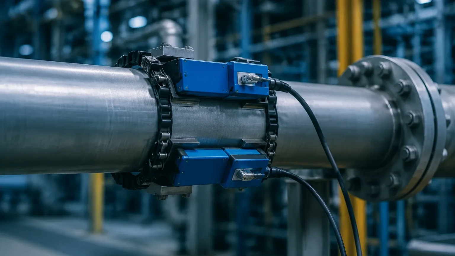
Correct installation is the single most important factor in the performance of a clamp on ultrasonic flow meter. Unlike inline meters, where the geometry is fixed at the factory, the "geometry" of a clamp-on system is established in the field.
Mounting Configurations
There are three common transducer mounting configurations, depending on the pipe diameter and fluid properties:
1. V-Method: The transducers are placed on the same side of the pipe. The signal bounces off the opposite wall. This is the standard method for pipe diameters ranging from 25 mm to 400 mm (1 to 16 inches).
2. Z-Method: The transducers are placed on opposite sides of the pipe. The signal crosses the pipe once. This is used for large pipes (typically over 400 mm) or when the fluid is highly attenuative, as it provides a shorter signal path.
3. W-Method: The signal bounces off the pipe walls three times. This is used for very small pipes (under 50 mm) to increase the signal path length and improve time-difference resolution.
Straight Pipe Requirements
To avoid errors caused by turbulence from valves, pumps, or elbows, engineers should follow the "10D Upstream / 5D Downstream" rule. This means the meter should be placed at a distance equal to at least 10 times the pipe diameter after any upstream disturbance and 5 times the diameter before any downstream disturbance. If space is limited, flow conditioners may be required.
Acoustic Coupling
Because air is a very poor conductor of high-frequency ultrasound, a coupling agent (grease, gel, or solid pads) must be applied between the transducer face and the pipe surface. This eliminates any air gaps and ensures maximum signal transfer. For permanent installations, high-temperature silicone or specialized epoxy resins are used to prevent the couplant from drying out over time.
Practical Selection and Comparison Table
When evaluating different models and technologies, the following table provides a reference for typical performance expectations across various industrial scenarios.
| Feature | Transit-Time Meter | Doppler Effect Meter |
| :— | :— | :— |
| Best Fluid Type | Clean liquids, water, oils, chemicals | Slurries, wastewater, aerated liquids |
| Solids/Bubbles Tolerance | < 2% by volume | > 100 ppm (minimum size ~100 microns) |
| Typical Accuracy | ±0.5% to ±2% of reading | ±2% to ±5% of full scale |
| Pipe Size Range | 10 mm to 6000 mm | 25 mm to 6000 mm |
| Installation Effort | Low (no pipe cutting) | Low (no pipe cutting) |
| Maintenance | Minimal (check couplant) | Minimal (check couplant) |
| Relative Cost | Moderate to High | Moderate |
Limitations and Common Operational Risks
While the clamp on ultrasonic flow meter is highly versatile, it is not a "one-size-fits-all" solution. Engineers must be aware of specific risks that can compromise data integrity.
Signal Attenuation
Certain pipe materials, such as ductile iron with thick cement linings or heavily corroded older pipes, can absorb or scatter the ultrasonic signal. In such cases, the signal-to-noise ratio may drop below the threshold required for a stable reading. Pre-installation testing with a portable meter is often recommended for older infrastructure.
Pipe Wall Thickness Uncertainty
The meter calculates flow based on the internal diameter of the pipe. If the wall thickness is unknown or incorrectly measured (e.g., due to internal scaling), the calculated cross-sectional area will be wrong, leading to a proportional error in the flow rate. Using an ultrasonic thickness gauge prior to installation is a best practice to mitigate this risk.
Ambient Noise and Vibration
High-frequency mechanical noise from nearby pumps or control valves can sometimes interfere with the ultrasonic signal. Modern digital signal processing (DSP) in high-end meters can filter out much of this noise, but shielding or relocating the sensors may be necessary in extreme environments.
Maintenance and Troubleshooting Best Practices
One of the primary benefits of clamp-on technology is the reduction in long-term maintenance. Since there are no moving parts and no contact with the process fluid, there is no wear and tear or chemical corrosion of the sensor elements. However, a routine inspection schedule should still be implemented.
* Couplant Integrity: Over several years, coupling gel can dry out or be washed away in outdoor environments. Periodically check the signal strength indicators on the meter display. A significant drop in signal strength often indicates that the couplant needs to be reapplied.
* Zero-Flow Calibration: Whenever possible, perform a zero-flow calibration during plant shutdowns. This involves ensuring the pipe is full of stagnant liquid and setting the meter to zero to eliminate any electronic offset.
* Transducer Alignment: Ensure that the mounting hardware has not loosened due to pipe vibration. Even a few millimeters of shift in transducer spacing can introduce significant measurement errors.
Integration with Level Measurement Systems
In many B2B industrial applications, flow measurement is only one part of the equation. For example, in chemical storage and distribution, a clamp on ultrasonic flow meter monitors the rate of transfer, while radar or ultrasonic level meters monitor the total volume remaining in the tanks.
Manufacturers like Welk specialize in these critical level measurement components, providing the data necessary to prevent overflows and manage inventory. By combining non-invasive flow data with precise level data, facility managers can achieve a complete mass balance of their operations. For those looking to explore high-reliability level sensors to pair with their flow systems, reviewing the technical specifications on the Main Page is a recommended next step in project planning.
Frequently Asked Questions (FAQs)
Q: Can a clamp on ultrasonic flow meter measure gas flow?
A: While most standard clamp-on meters are designed for liquids, specialized high-power ultrasonic meters exist for gas applications. However, gas measurement is significantly more challenging due to the low density of the medium and high signal attenuation.
Q: Does the pipe need to be full?
A: Yes, for accurate measurement, the pipe must be completely full of liquid. If the pipe is partially full, the ultrasonic signal will not travel correctly between the transducers, and the cross-sectional area calculation will be invalid.
Q: How does pipe scale affect the measurement?
A: Internal scaling or buildup effectively reduces the internal diameter of the pipe. Since the meter assumes a fixed diameter based on the initial setup, scaling will cause the meter to over-report the flow rate. If scaling is suspected, the meter's internal diameter setting may need periodic adjustment based on manual verification.
Q: Can these meters be used on plastic pipes?
A: Yes, ultrasonic waves travel very well through most plastics, including PVC, HDPE, and PP. They are often easier to measure through than metallic pipes because there is less signal reflection at the pipe-wall interface.
Conclusion
The clamp on ultrasonic flow meter represents a pinnacle of non-intrusive instrumentation, providing industrial operators with a flexible, accurate, and cost-effective method for flow monitoring. By understanding the underlying physics of transit-time and Doppler measurement, and by adhering to strict installation guidelines regarding pipe geometry and acoustic coupling, engineering teams can ensure long-term reliability. When integrated with robust level measurement solutions, these instruments form the backbone of modern, efficient industrial process control.