Conductivity Measuring Unit
Conductivity Measuring Unit
In industrial process control, the ability to quantify the electrical properties of a liquid is fundamental to ensuring product quality, system safety, and operational efficiency. A conductivity measuring unit serves as the primary tool for this task, providing real-time data on the ionic concentration of a solution. Whether used in ultrapure water production, chemical concentration monitoring, or as a component in conductive level detection, understanding the principles and selection criteria of these units is essential for plant engineers and system integrators.
Conductivity is a measure of a material's ability to conduct an electrical current. In aqueous solutions, this ability is provided by dissolved ions—such as salts, acids, or bases. By measuring the electrical conductance of a liquid, a conductivity measuring unit can infer the total dissolved solids (TDS) or the concentration of specific chemicals within a process stream.
Measurement Principles
Before selecting a conductivity measuring unit, it is vital to understand the two primary physical principles used to capture this data: contacting (conductive) measurement and inductive (toroidal) measurement.
Contacting Conductivity Measurement
Contacting sensors utilize two or more electrodes that come into direct physical contact with the process liquid. An alternating voltage is applied between the electrodes, and the resulting current is measured. According to Ohm’s Law, the conductance is the reciprocal of resistance. To determine the specific conductivity of the liquid, the device accounts for the geometry of the electrodes, known as the "cell constant" ($K$).
Contacting sensors are highly sensitive and are the preferred choice for low-conductivity applications, such as deionized water or steam condensate. However, because the electrodes are exposed, they are susceptible to fouling, scaling, and corrosion, which can degrade measurement accuracy over time.
Inductive (Toroidal) Conductivity Measurement
Inductive sensors, often called electrodeless or toroidal sensors, use two induction coils encased in a non-conductive plastic or ceramic housing. The first coil (the transmitter) generates an alternating magnetic field that induces an electric current in the surrounding liquid. This current, in turn, induces a voltage in the second coil (the receiver). The magnitude of this induced voltage is proportional to the conductivity of the liquid.
Because the internal components never touch the process medium, inductive units are virtually immune to fouling and chemical attack. They are ideal for high-conductivity liquids, slurries, and highly corrosive chemicals like concentrated acids or alkalis.
Understanding Conductivity Units and Scales
The standard international (SI) unit for conductivity is Siemens per meter (S/m). However, in industrial practice, smaller sub-units are more common to provide readable scales for specific applications. The most frequently encountered units include:
* Microsiemens per centimeter (µS/cm): Used for low-conductivity liquids like distilled water (0.5 to 5 µS/cm) or tap water (50 to 800 µS/cm).
* Millisiemens per centimeter (mS/cm): Used for high-conductivity liquids, such as seawater (~50 mS/cm) or industrial acids.
* TDS (Parts Per Million – PPM): While not a direct conductivity unit, many meters convert conductivity to PPM using a conversion factor (typically 0.5 to 0.7) to estimate the mass of dissolved solids.
* Resistivity (MΩ·cm): The inverse of conductivity, often used in the semiconductor and pharmaceutical industries to measure the purity of ultrapure water. 18.2 MΩ·cm is the theoretical limit for pure water.
Selection Criteria for Industrial Applications
Choosing the correct conductivity measuring unit requires an evaluation of the process environment and the required precision. Engineers should consult the Main Page of technical providers to compare specific sensor specifications against these key criteria:
1. The Cell Constant ($K$)
The cell constant is the ratio of the distance between electrodes ($L$) to the cross-sectional area of the electrodes ($A$).
* Low Cell Constant ($K=0.01$ to $0.1$): Best for high-purity water.
* Medium Cell Constant ($K=1.0$): Suitable for general-purpose water treatment.
* High Cell Constant ($K=10$ or Inductive): Required for concentrated chemicals and wastewater.
2. Temperature Compensation
Conductivity is highly temperature-dependent. Most aqueous solutions exhibit a conductivity increase of approximately 2% for every 1°C increase in temperature. A reliable conductivity measuring unit must include an integrated temperature sensor (such as a Pt100 or Pt1000) and sophisticated software to normalize the reading to a reference temperature, typically 25°C.
3. Material Compatibility
For contacting sensors, electrode materials must resist the chemical properties of the fluid. Common materials include 316L stainless steel, titanium, and graphite. For inductive sensors, the outer casing (often PEEK, PFA, or PP) must be compatible with the process temperature and chemical aggressiveness.
Conductivity in Level Measurement
One of the most practical applications of conductivity in industrial automation is point level detection. Conductive level switches utilize the liquid's own conductivity to complete an electrical circuit. When the liquid reaches the level of a probe, a small current flows between the probe and the tank wall (or a reference probe), triggering a relay.
This method is cost-effective and highly reliable for conductive liquids like water, beer, acids, and milk. Unlike float switches, conductive level probes have no moving parts, making them suitable for applications with high agitation or where mechanical failure must be avoided.
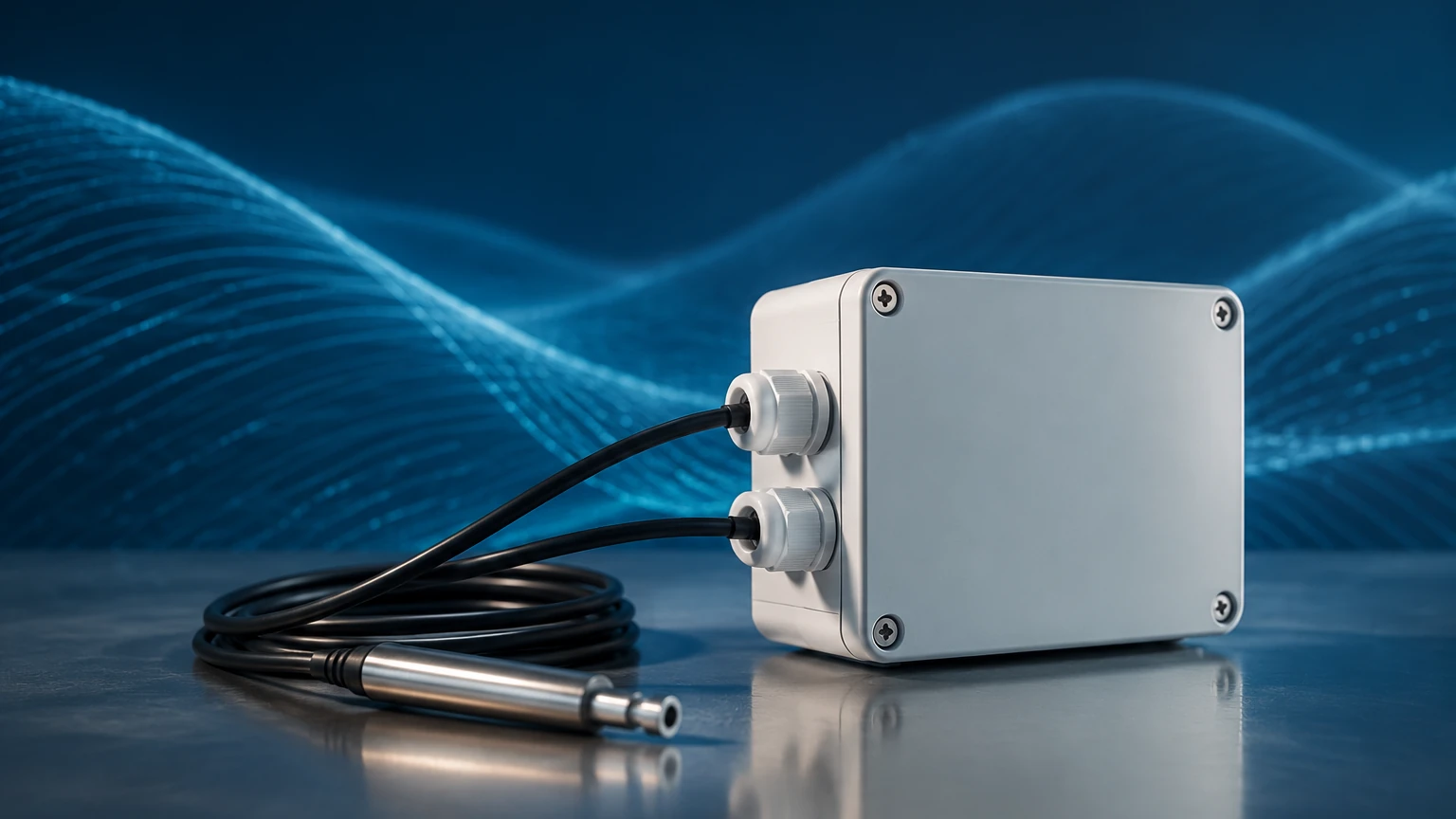
Comparison Table: Contacting vs. Inductive Sensors
| Feature | Contacting Sensors | Inductive (Toroidal) Sensors |
| :— | :— | :— |
| Measurement Range | 0.01 µS/cm to 20 mS/cm | 100 µS/cm to 2,000 mS/cm |
| Best Application | Ultrapure water, condensate | Acids, bases, brine, wastewater |
| Fouling Resistance | Low (easily coated) | High (no exposed electrodes) |
| Installation Size | Usually small/compact | Larger diameter required |
| Maintenance | Periodic cleaning/calibration | Minimal maintenance required |
Installation and Engineering Considerations
To ensure the longevity and accuracy of a conductivity measuring unit, several installation factors must be addressed:
1. Avoid Air Bubbles: Conductivity sensors must be fully submerged. Air bubbles trapped against the electrode or inside the toroidal bore will result in artificially low readings. In horizontal pipes, sensors should be installed on the side or bottom, never at the top.
2. Flow Velocity: While some flow is necessary to ensure a representative sample, excessive velocity can cause cavitation or physical wear on the sensor. Conversely, stagnant flow can lead to sediment buildup.
3. Electrical Interference: Conductivity signals are low-voltage and can be affected by electromagnetic interference (EMI) from large motors or variable frequency drives (VFDs). Shielded cabling and proper grounding are mandatory.
4. Pipe Sizing for Inductive Sensors: Inductive sensors require a minimum clearance (the "wall effect") to prevent the pipe walls from interfering with the magnetic field. If installed in a plastic pipe, the field extends further than in a metallic pipe.
Maintenance and Calibration
Even the most robust conductivity measuring unit requires periodic verification. Calibration is typically performed using standard conductivity solutions (e.g., Potassium Chloride – KCl) that have a known, stable conductivity at specific temperatures.
* Cleaning: For contacting sensors, oils can be removed with a mild detergent, while scales (calcium carbonate) may require a weak acid solution (5% HCl).
* Zero Calibration: Performed in dry air to ensure the meter reads zero when no conductive path is present.
* Slope Calibration: Performed using a standard solution that closely matches the expected process value.
Frequently Asked Questions (FAQ)
Q: Can a conductivity measuring unit be used to measure the level of oil or hydrocarbons?
A: Generally, no. Oils and hydrocarbons are non-conductive (dielectric) liquids. For these applications, capacitive, ultrasonic, or radar level meters are required. Conductive level switches only work with liquids having a conductivity typically above 5-10 µS/cm.
Q: How often should I calibrate my conductivity sensor?
A: This depends on the process. In stable, clean water applications, semi-annual calibration may suffice. In harsh chemical processes where fouling is likely, monthly or even weekly verification may be necessary to maintain accuracy.
Q: What is the difference between 2-electrode and 4-electrode contacting sensors?
A: 2-electrode sensors are simpler and best for low conductivity. 4-electrode sensors use two electrodes to drive the current and two to measure the voltage drop, which helps eliminate errors caused by polarization and cable resistance in higher conductivity ranges.
Q: Does the pipe material affect the measurement?
A: For contacting sensors, the pipe material is irrelevant as long as the sensor is properly grounded. For inductive sensors, a metallic pipe acts as part of the electrical circuit and must be accounted for during the initial setup and calibration of the unit.
By carefully selecting a conductivity measuring unit based on the chemical environment, required range, and maintenance capabilities, industrial operators can achieve precise control over their liquid processes. Whether used for monitoring water purity or managing chemical dosing, these instruments remain a cornerstone of modern process engineering.