Clear Well
Clear Well
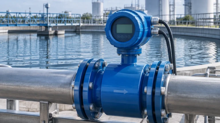
In the infrastructure of municipal and industrial water treatment, the clear well serves as the final critical buffer between the treatment process and the distribution network. As a storage reservoir for treated, potable water, the clear well provides the necessary contact time for disinfectants and balances the constant output from the treatment plant against the fluctuating demands of the consumer grid.
Accurate level measurement within a clear well is not merely a matter of inventory management; it is a fundamental requirement for process safety, regulatory compliance, and pump efficiency. Monitoring the level ensures that high-service pumps do not run dry, prevents the overflow of treated water, and maintains the hydraulic head required for distribution. This guide examines the technical principles, selection criteria, and installation best practices for level instrumentation in clear well applications.
Understanding the Role of the Clear Well in Water Treatment
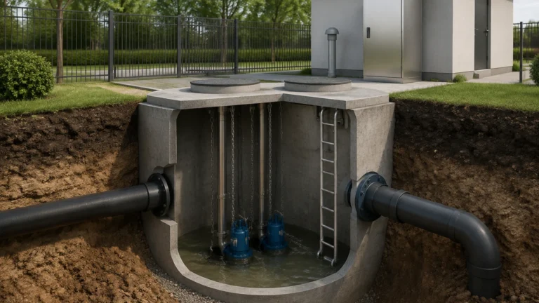
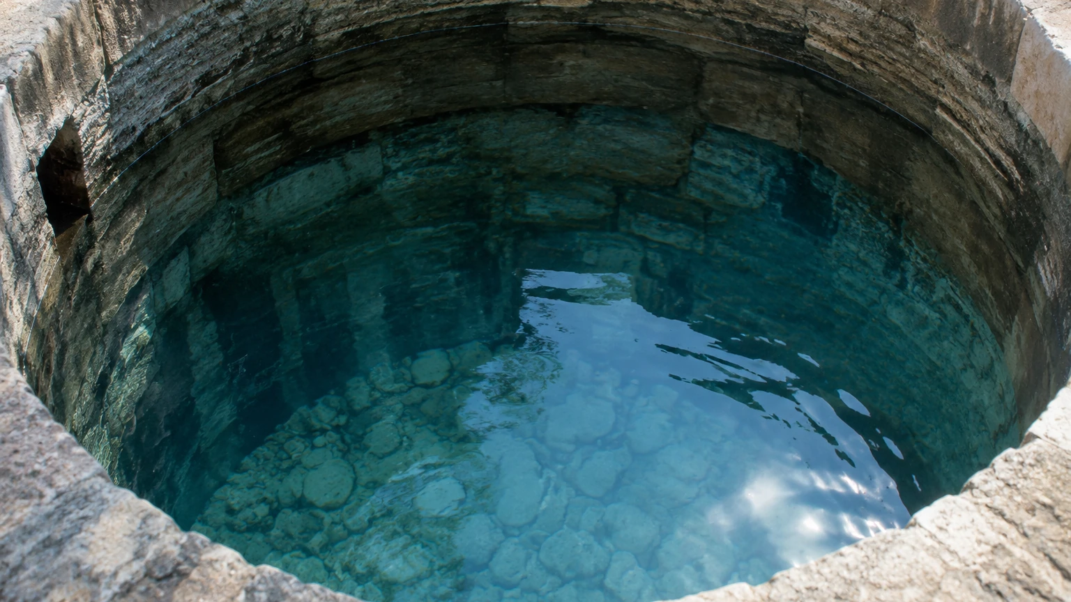
A clear well is a large tank or underground basin designed to hold filtered water. Its primary functions include providing chlorine contact time (CT) to ensure complete disinfection and acting as a surge tank to accommodate variations in demand. Because clear wells are often the last point of control before water enters the public supply, the reliability of the instrumentation used here is paramount.
Level measurement in these facilities must account for various physical factors, including the large surface area of the basins, potential turbulence near inlet and outlet pipes, and the high humidity levels common in enclosed storage structures. Selecting the right technology depends on the physical layout of the well, the required accuracy, and the integration requirements of the facility's SCADA system.
Core Principles of Level Measurement in Clear Wells
To select the most appropriate instrument, engineers must first understand the physical principles governing different measurement technologies. In clear well applications, the three most common methods are ultrasonic (non-contact), radar (non-contact), and hydrostatic (contact).
Ultrasonic Level Measurement
Ultrasonic sensors operate on the "Time of Flight" (ToF) principle. The sensor emits a high-frequency sound pulse that travels through the air, reflects off the water surface, and returns to the transducer. The instrument calculates the distance based on the time elapsed and the speed of sound in air.
* Advantages: Non-contact, relatively low cost, and easy to install in open or vented basins.
* Limitations: The speed of sound is affected by air temperature and humidity. While most modern sensors include temperature compensation, extreme fluctuations or heavy fog/vapor in the clear well can attenuate the signal.
Radar Level Measurement
Radar sensors also use the Time of Flight principle but employ electromagnetic waves (microwaves) rather than sound. These waves travel at the speed of light and reflect off the surface of the water due to the change in dielectric constant between the air and the liquid.
* Advantages: Unaffected by air temperature, pressure, vacuum, or vapors. High-frequency radar (e.g., 80 GHz) offers a narrow beam angle, which is ideal for avoiding internal obstructions like ladders or support beams in the clear well.
* Limitations: Higher initial capital expenditure compared to ultrasonic or hydrostatic methods, though this is often offset by lower maintenance costs.
Hydrostatic Level Measurement
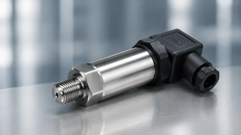
Hydrostatic sensors are submersible pressure transmitters. They are lowered to the bottom of the clear well and measure the pressure exerted by the column of water above them. This pressure is directly proportional to the liquid height (P = ρgh).
* Advantages: Simple to install, unaffected by surface foam or turbulence, and highly reliable for deep wells or underground basins where mounting a sensor at the top is difficult.
* Limitations: It is a contact-based method. The sensor and cable are submerged in treated water, requiring materials that are compatible with potable water standards (e.g., NSF/ANSI 61).
Comparative Analysis of Level Measurement Technologies
When evaluating options for a clear well project, engineers should compare technologies based on the specific constraints of the site. The following table provides a high-level comparison of the primary technologies used in these applications.
| Feature | Ultrasonic | Radar (80 GHz) | Hydrostatic |
| :— | :— | :— | :— |
| Measurement Type | Non-contact | Non-contact | Contact (Pressure) |
| Accuracy | ±0.25% of range | ±1 mm to ±2 mm | ±0.1% to ±0.5% of range |
| Influence of Vapor/Fog | High | None | None |
| Influence of Temperature | Moderate (Compensated) | None | Low |
| Installation Ease | High | High | Moderate (Requires cable support) |
| Maintenance | Low | Very Low | Moderate (Periodic cleaning) |
| Typical Cost | $ | $$$ | $$ |
For comprehensive technical specifications and to explore specific instrument models, engineers can Review product options and application support to find the best fit for their infrastructure requirements.
Engineering Considerations for Clear Well Installation
The physical environment of a clear well presents unique challenges that can interfere with sensor performance. Proper installation is as important as selecting the correct technology.
1. Avoiding Internal Obstructions
Clear wells often contain structural supports, baffles, and ladders. For non-contact sensors (ultrasonic and radar), the "beam angle" is a critical specification. If the beam hits a structural element, it will create a false echo. Using high-frequency radar with a narrow beam (typically 3 to 8 degrees) allows the sensor to be mounted closer to walls or near obstructions without signal interference.
2. Managing Turbulence and Inlets
Water entering the clear well can create surface turbulence or foam. If a sensor is mounted directly above an inlet pipe, the reading may fluctuate wildly. It is best practice to install level sensors in a "quiet zone" of the tank. If the entire surface is turbulent, a stilling well (a vertical pipe that dampens surface movement) may be required for ultrasonic or radar sensors. Hydrostatic sensors are naturally less affected by surface turbulence but should be anchored to prevent the sensor from moving in high-flow areas.
3. Humidity and Condensation
Clear wells are enclosed environments with 100% humidity. In non-contact sensors, condensation can form on the transducer face. While many modern radar sensors use PTFE or other drip-off designs to shed water droplets, ultrasonic sensors may struggle if water builds up on the vibrating face. Ensuring the sensor is mounted at a slight angle or selecting a model with a high-gain signal can mitigate these effects.
4. Stilling Wells and Bypass Chambers
In cases where the clear well surface is consistently covered in foam or is extremely turbulent, a stilling well is recommended. This is a pipe (typically PVC or Stainless Steel) that extends into the water. The sensor is mounted at the top of the pipe, and the water level inside the pipe remains stable and representative of the tank level. This is particularly useful for radar applications where high accuracy is required despite surface disturbances.
Addressing Environmental and Operational Challenges
Chemical Compatibility
Although clear wells contain "clean" water, the presence of residual chlorine or chloramines can be corrosive over long periods. For hydrostatic sensors, the housing should be made of high-grade stainless steel (316L) or titanium, and the cable jacket should be made of Polyurethane (PUR) or FEP. For non-contact sensors, the wetted parts (the face of the sensor) are typically plastic or encapsulated in a protective housing.
Lightning and Surge Protection
Because clear wells are often located in open areas or are part of large metallic structures, they are susceptible to lightning strikes. Level transmitters should be equipped with integrated surge protection, and the signal loop (typically 4-20mA) should be protected by surge arrestors at the PLC/SCADA entry point.
Redundancy and Safety
In many municipal applications, a single level sensor is not sufficient for safety-critical operations. A common configuration includes one continuous level transmitter (radar or hydrostatic) for process control and one or two point-level switches (float switches or tuning forks) for high-high and low-low level alarms. This redundancy ensures that if the primary transmitter fails, the pumps will still be protected from running dry or causing an overflow.
Maintenance and Lifecycle Management
While modern electronic level meters are designed for long-term stability, a routine maintenance schedule is essential for ensuring continued accuracy in a clear well environment.
1. Visual Inspection: Every 6 to 12 months, inspect non-contact sensors for buildup of condensation, spider webs, or debris on the transducer face. For hydrostatic sensors, check the cable for signs of wear or chemical degradation.
2. Calibration Verification: Perform a "dip tape" measurement to verify the electronic reading against the physical water level. If the deviation exceeds the allowable tolerance (typically 0.1% to 0.5% depending on the sensor), a recalibration may be necessary.
3. Venting Check: Hydrostatic sensors use a vent tube in the cable to compensate for changes in atmospheric pressure. Ensure the desiccant cartridge at the end of the vent tube is fresh (usually indicated by a color change from blue to pink) to prevent moisture from entering the sensor electronics.
Frequently Asked Questions
Q: Can I use a float switch for clear well level control?
A: While float switches are useful for simple high/low alarms, they do not provide continuous data. For efficient pump management and CT (Contact Time) calculations, a continuous level transmitter (radar, ultrasonic, or hydrostatic) is required.
Q: How does temperature affect clear well level readings?
A: In ultrasonic systems, temperature changes the speed of sound, which can lead to errors of several centimeters if not compensated. Radar and hydrostatic systems are virtually unaffected by the air temperature changes typically found in water treatment facilities.
Q: What is the best mounting location for a sensor in a clear well?
A: The sensor should be mounted away from the inlet (to avoid turbulence), away from the walls (to avoid signal interference), and in a location that is easily accessible for maintenance. It should also be positioned above the deepest part of the well to ensure the full range is measured.
Q: Is 80 GHz radar better than 26 GHz radar for clear wells?
A: Generally, yes. 80 GHz radar provides a much narrower beam, which is better for avoiding the internal structures and narrow manways often found in clear well designs. It also handles condensation on the lens more effectively than lower-frequency models.
Conclusion
Effective level management in a clear well is a cornerstone of reliable water distribution. By understanding the principles of ultrasonic, radar, and hydrostatic measurement, engineers can select the technology that best balances cost, accuracy, and maintenance requirements. Whether upgrading an existing facility or designing a new treatment plant, focusing on proper installation and environmental factors will ensure that the clear well continues to function as a dependable buffer for the community's water supply. For further assistance in selecting the appropriate instrumentation for your specific application, you can Review product options and application support to ensure your system meets the highest standards of industrial automation.