Hydrostatic Pressure Transmitter
Hydrostatic Pressure Transmitter
In the field of industrial process control, the hydrostatic pressure transmitter remains one of the most reliable and widely adopted technologies for liquid level measurement. By leveraging the fundamental laws of physics—specifically the relationship between the height of a liquid column and the pressure it exerts—these instruments provide a robust solution for monitoring water, chemicals, oils, and various industrial fluids. This guide examines the engineering principles, selection criteria, and installation best practices essential for technical professionals and system integrators.
Understanding the Principle of Hydrostatic Level Measurement
The operation of a hydrostatic pressure transmitter is based on Pascal’s Law, which states that the pressure exerted by a static liquid column is directly proportional to its height and the density of the fluid. This is mathematically expressed by the formula:
P = ρ × g × h
Where:
* P is the hydrostatic pressure (measured in Pascals or bar).
* ρ (rho) is the density of the liquid (kg/m³).
* g is the local acceleration due to gravity (approximately 9.81 m/s²).
* h is the height of the liquid column (meters).
Because gravity is a constant and the density of the liquid is typically known, the transmitter can accurately calculate the level (h) by measuring the pressure (P). The sensor converts this physical pressure into an electrical signal, most commonly a 4-20mA analog output or a digital protocol like HART or RS485. It is important to note that this measurement is "weight-dependent." If the density of the liquid changes—due to temperature fluctuations or concentration shifts—the transmitter will report a change in level even if the physical height remains the same. Therefore, density compensation is a critical consideration in high-precision applications.
Types of Hydrostatic Pressure Transmitters
Depending on the tank geometry and the nature of the media, hydrostatic transmitters are generally categorized into two primary designs: submersible and externally mounted.
1. Submersible Level Transmitters
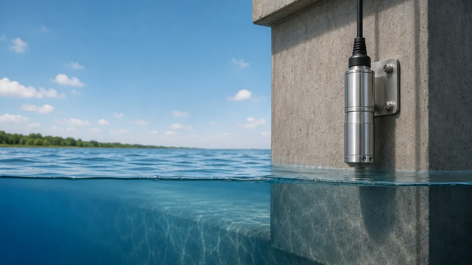
These units are designed to be lowered directly into the liquid. The sensor is housed in a waterproof casing, typically made of 316L stainless steel or specialized plastics for corrosive environments.
* Vented Cable: A unique feature of submersible transmitters is the integration of a capillary vent tube within the signal cable. This tube allows the sensor to reference the atmospheric pressure above the liquid, ensuring that changes in barometric pressure do not skew the level reading.
* Applications: Ideal for deep wells, boreholes, open reservoirs, and wastewater sumps where bottom-entry mounting is not feasible.
2. Externally Mounted (Flanged or Threaded) Transmitters
These transmitters are installed on the outside of a tank or vessel, usually at the lowest possible point. The process media comes into contact with a sensing diaphragm through a threaded connection or a mounting flange.
* Maintenance Advantage: Since the transmitter is outside the tank, it can often be serviced or replaced without draining the vessel, provided an isolation valve is installed.
* Applications: Common in chemical storage tanks, food and beverage processing, and industrial buffer tanks.
Key Technical Specifications and Evaluation Criteria
When specifying a hydrostatic pressure transmitter for a project, engineers must evaluate several technical parameters to ensure long-term reliability and accuracy.
| Feature | Consideration | Why it Matters |
| :— | :— | :— |
| Measuring Range | 0–1m to 0–200m H₂O | Selecting a range too high reduces resolution; too low risks overpressure damage. |
| Wetted Materials | 316L SS, Hastelloy, Ceramic, PTFE | Must be chemically compatible with the media to prevent corrosion or diaphragm failure. |
| Accuracy Class | 0.1%, 0.25%, or 0.5% FS | Higher accuracy is required for custody transfer or precise batching processes. |
| Output Signal | 4-20mA, 0-10V, HART, Modbus | Determines compatibility with the PLC, DCS, or remote monitoring system. |
| Ingress Protection | IP68 (Submersible) or IP65/67 | Ensures the electronics are protected from moisture and dust. |
Material Compatibility
For standard water applications, 316L stainless steel is the industry standard. However, in wastewater treatment or chemical processing, the presence of chlorides or acids may require a ceramic diaphragm or a PTFE (Teflon) coating. Ceramic sensors are particularly valued for their abrasion resistance when measuring slurries or liquids with suspended solids.
Practical Selection Guide for Industrial Applications
Selecting the right instrument involves matching the transmitter's capabilities to the specific environmental challenges of the site.
1. Water and Wastewater: For sewage lift stations, a submersible transmitter with a large, non-clogging diaphragm is preferred. The cable should be made of polyurethane (PUR) or PVC to withstand the fats, oils, and greases (FOG) found in effluent.
2. Chemical Storage: In vented tanks containing corrosive acids, an externally mounted transmitter with a PTFE-lined flange is often the safest choice. This prevents the sensitive electronics from being exposed to corrosive vapors inside the tank headspace.
3. Oil and Gas: Applications involving fuels or flammable chemicals require intrinsically safe (Ex ia) or explosion-proof (Ex d) certifications to comply with ATEX or IECEx standards.
For engineers looking to compare specific models or request customized OEM configurations, it is helpful to Review product options and application support on the Welk Main Page to ensure the hardware meets local regulatory and technical requirements.
Installation Guidelines and Best Practices
Correct installation is as important as selecting the right hardware. Poor placement can lead to signal noise, premature failure, or inaccurate readings.
Submersible Installation
* Avoid Turbulence: Do not install the sensor directly near an inlet pipe or an agitator. The moving fluid can create dynamic pressure, which the sensor will interpret as a level change. If turbulence is unavoidable, use a "stilling well" (a perforated pipe) to shield the sensor.
* Cable Protection: Ensure the cable is secured with a proper suspension clamp. The weight of the sensor and cable should not be supported by the electrical connections.
* Venting Protection: The end of the vent tube must be located in a dry area. A desiccant box or a specialized vent filter should be used to prevent moisture from entering the tube, which can lead to internal condensation and sensor drift.
Externally Mounted Installation
* Zero Point Calibration: The transmitter should be installed as close to the tank bottom as possible. Any distance between the sensor and the true bottom of the tank (the "dead zone") must be accounted for in the PLC or the transmitter's zero-offset settings.
* Isolation Valves: Always install a ball valve or needle valve between the tank and the transmitter. This allows for calibration checks and maintenance without interrupting the process.
Limitations and Common Operational Risks
While highly versatile, the hydrostatic pressure transmitter is not a universal solution. Understanding its limitations prevents common engineering errors.
* Pressurized Vessels: A standard hydrostatic transmitter cannot be used in a sealed, pressurized tank. In such cases, the sensor would measure the sum of the liquid pressure and the gas headspace pressure. For these applications, a Differential Pressure (DP) transmitter is required to subtract the headspace pressure.
* Density Fluctuations: As mentioned, these sensors measure mass. If a tank is used for different liquids with varying densities, the system must be recalibrated, or a secondary sensor must be used to provide real-time density compensation.
* Temperature Extremes: Rapid temperature changes can affect the elasticity of the sensing diaphragm. While most modern transmitters include internal temperature compensation, extreme heat may require the use of a capillary-style remote seal to move the electronics away from the heat source.
Frequently Asked Questions (FAQs)
Q: How often should a hydrostatic pressure transmitter be calibrated?
A: For most industrial applications, an annual calibration check is sufficient. However, in critical processes or harsh environments where drift is more likely, semi-annual checks are recommended.
Q: Can I cut the cable of a submersible transmitter to fit my tank?
A: Most cables can be shortened, but it is critical not to damage or block the internal vent tube. It is generally better to order the transmitter with the correct cable length or to coil the excess cable neatly in a junction box.
Q: What is the difference between "gauge pressure" and "absolute pressure" in level measurement?
A: Most level applications use gauge pressure transmitters, which are vented to the atmosphere. Absolute pressure transmitters are referenced to a vacuum and are rarely used for liquid level unless the tank is sealed and the atmospheric pressure is measured separately.
Q: How do I protect the sensor from lightning strikes in outdoor reservoirs?
A: Submersible transmitters used in open water should be equipped with integrated surge protection. Additionally, the signal loop should include a surge protector at the control panel end.
By following these technical guidelines and understanding the physical constraints of the technology, operators can ensure that their hydrostatic pressure transmitter provides accurate, maintenance-free service for years. For more detailed technical data and specific instrument comparisons, visiting the Main Page provides access to comprehensive product specifications and engineering support.