Composite Sampler Wastewater
Composite Sampler Wastewater
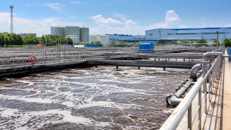
In industrial and municipal water treatment, obtaining a representative snapshot of effluent quality is critical for regulatory compliance, process optimization, and environmental protection. A composite sampler for wastewater is a specialized instrument designed to collect multiple discrete samples over a defined period and combine them into a single container. This process provides a "composite" view of the wastewater characteristics, smoothing out the fluctuations in concentration and flow that occur throughout a production cycle or a 24-hour day.
Unlike grab sampling, which only provides data for a specific moment in time, composite sampling allows engineers to calculate the Total Daily Load (TDL) of pollutants such as Biochemical Oxygen Demand (BOD), Chemical Oxygen Demand (COD), Total Suspended Solids (TSS), and heavy metals. To ensure the accuracy of these samples, the integration of precise level and flow measurement instruments is often required.
Measurement Principles of Composite Samplers
Before selecting a system, it is essential to understand how these devices initiate and execute the sampling process. Composite samplers generally operate based on two primary pacing methods: time-proportional and flow-proportional.
Time-Proportional Sampling
In this mode, the sampler is programmed to collect a fixed volume of wastewater at regular, pre-set time intervals (e.g., 200 mL every 30 minutes). This method is simplest to implement but is only accurate if the flow rate of the wastewater remains relatively constant. If flow varies significantly, time-proportional sampling may over-represent periods of low flow and under-represent periods of high flow in the final composite mixture.
Flow-Proportional Sampling
Flow-proportional sampling is the industry standard for dynamic environments. The sampler collects volumes based on the actual amount of water passing through a channel or pipe. This requires an external signal from a flow meter or a level transmitter installed over a primary device like a flume or weir. There are two sub-types:
1. Constant Volume / Variable Time (CVVT): The sampler takes a fixed volume (e.g., 100 mL) every time a specific volume of water (e.g., 5,000 liters) passes the sensor.
2. Variable Volume / Constant Time (VVCT): The sampler takes samples at fixed time intervals, but the volume of each sample is scaled according to the flow rate at that moment.
Sample Extraction Mechanisms
Most modern composite samplers use one of two extraction methods:
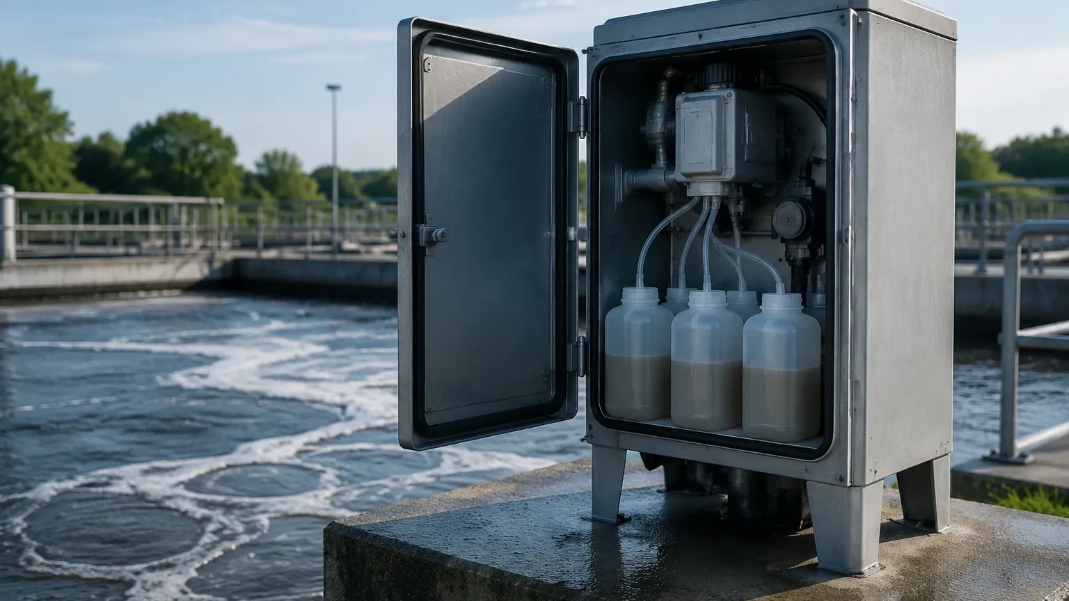
* Peristaltic Pump: A rotating roller compresses a flexible tube to create a vacuum, drawing the liquid up. This is the most common method due to its ease of maintenance and ability to handle suspended solids.
* Vacuum-Compression: Uses a vacuum pump to draw the sample into a calibrated chamber. This method is often preferred for high-lift applications (up to 8 or 9 meters) and provides high transport velocities to prevent solids from settling in the intake tube.
Integration with Level and Flow Measurement
For a composite sampler in wastewater applications to function effectively in flow-proportional mode, it must be paired with accurate primary measurement hardware. Industrial manufacturers like Welk provide the foundational technology needed to trigger these samplers.
In open channel applications, ultrasonic level sensors or radar level meters are mounted above flumes (such as Parshall or Palmer-Bowlus) or weirs. The level instrument measures the head height of the water, and the internal electronics convert this height into a flow rate based on programmed discharge curves. The level meter then sends a pulse or a 4-20mA signal to the composite sampler.
When the accumulated flow reaches the user-defined threshold, the sampler initiates a cycle. For more information on the sensors used to drive these systems, you can Review product options and application support on the Welk Main Page.
Selection Criteria for Wastewater Samplers
Choosing the right equipment depends on the specific chemical nature of the wastewater, the physical environment, and regulatory requirements. The following table outlines the key differences between common sampler configurations.
Selection Comparison Table
| Feature | Portable Samplers | Stationary Samplers | Refrigerated Samplers |
| :— | :— | :— | :— |
| Primary Use | Short-term studies, remote sites | Permanent discharge points | Regulatory compliance (EPA/ISO) |
| Power Source | 12V DC Battery / Solar | 110V/220V AC | 110V/220V AC |
| Sample Preservation | Ice / Insulated base | None (Ambient) | Active Compressor (4°C) |
| Mobility | High (Lightweight) | Low (Bolted down) | Low |
| Housing Material | Heavy-duty Plastic (PE) | Stainless Steel / GRP | Stainless Steel / Plastic |
| Typical Lift | 6 – 8 meters | 6 – 9 meters | 6 – 9 meters |
Key Evaluation Factors
1. Sample Preservation: Many biological and chemical parameters require the sample to be kept at 4°C (±1°C) to inhibit biological activity and chemical degradation. In these cases, a refrigerated sampler is mandatory.
2. Bottle Configuration: Samplers can be configured with a single large composite bottle (e.g., 10L or 20L) or multiple discrete bottles (e.g., 24 x 1L). Multiple bottles allow for "first flush" analysis or identifying exactly when a spill occurred during a 24-hour cycle.
3. Suction Lift: Ensure the pump can handle the vertical distance between the sampler and the lowest water level. Standard peristaltic pumps typically handle up to 7 meters of lift.
4. Chemical Compatibility: If the wastewater contains aggressive solvents or acids, the intake tubing (typically PVC or Silicone) and the strainer must be checked for compatibility.
Installation and Engineering Considerations
Proper installation is as important as the instrument itself. Poorly placed intake lines can lead to biased samples that do not reflect the true state of the wastewater.
Intake Line Placement
* Representative Location: The intake strainer should be placed in a well-mixed area of the channel, typically at 60% of the depth from the surface. Avoid areas of stagnant water or excessive turbulence.
* Velocity: The intake velocity should be at least 0.5 meters per second (m/s) to ensure that suspended solids are captured and do not settle out in the tubing.
* Avoid Loops: The suction line should have a continuous downward slope toward the source. Any loops or "low spots" in the tubing will trap liquid between samples, leading to cross-contamination.
Environmental Protection
Stationary samplers should be installed on a level concrete pad. If the wastewater contains flammable vapors (common in refinery or chemical plant sewers), the sampler must be rated for hazardous areas (ATEX/IECEx) or placed in a purged enclosure.
Power and Communication
For flow-proportional sampling, ensure the signal cable from the level/flow meter is shielded to prevent electromagnetic interference (EMI) from nearby pumps or motors. If using a portable sampler in a remote manhole, calculate the battery life based on the expected number of samples and the power draw of the cooling system if applicable.
Limitations and Operational Risks
While composite samplers are robust, they have inherent limitations that engineers must manage:
* Large Solids: Wastewater often contains debris. If the intake strainer openings are too small, they will clog; if they are too large, they may allow debris to damage the pump tubing. Typical strainer holes are 3mm to 9mm.
* Volatile Organic Compounds (VOCs): The vacuum or peristaltic action of the sampler can cause "off-gassing" of volatile components. For VOC analysis, grab samples are usually preferred over composite samples collected via suction.
* Cross-Contamination: Even with a "pre-purge" and "post-purge" cycle (where the pump runs in reverse to clear the line), a small amount of residual liquid may remain in the tubing. In high-precision applications, tubing should be replaced regularly.
* Temperature Extremes: In very cold climates, intake lines must be heat-traced or insulated to prevent freezing. In extremely hot climates, non-refrigerated samplers will fail to keep samples at the required 4°C.
Frequently Asked Questions (FAQs)
Q: How often should I calibrate the sampler volume?
A: Volume calibration should be performed at least monthly or whenever the suction tubing is replaced. Changes in tubing elasticity affect the volume delivered by peristaltic pumps.
Q: Can I use a composite sampler for oil and grease analysis?
A: Generally, no. Oil and grease tend to coat the intake tubing and the sample container walls, leading to inaccurate results. Regulatory agencies typically require discrete grab samples in glass containers for oil and grease testing.
Q: What is the maximum distance for the intake line?
A: While some pumps can pull from 20-30 meters horizontally, it is best to keep the line as short as possible (under 10 meters) to minimize the risk of solids settling and to reduce the strain on the pump motor.
Q: How does the sampler know the flow rate?
A: It receives a signal from an external meter. For example, a Welk ultrasonic level transmitter measures the height in a flume and sends a pulse to the sampler for every 1,000 liters. The sampler counts these pulses and triggers when the target is reached.
Conclusion
A composite sampler for wastewater is a vital tool for any facility required to monitor its environmental impact. By understanding the principles of flow-proportional sampling and ensuring the system is integrated with reliable level measurement technology, operators can ensure their data is both accurate and defensible. When selecting a system, always prioritize the physical characteristics of your sampling site—specifically lift height and power availability—and ensure the preservation method meets your local regulatory standards.