Condensate Sensor
Condensate Sensor
In industrial thermal management and steam process systems, the effective monitoring of condensate is a critical factor for operational efficiency, equipment longevity, and safety. A condensate sensor is not a single type of device but rather a category of level measurement instruments designed to detect the presence, volume, or level of condensed water within tanks, sumps, steam traps, and heat exchangers.
Condensate is the liquid phase of a substance, such as water, that has been condensed from its particulate or gaseous state. In steam systems, this liquid is essentially distilled water, often at high temperatures and pressures. Managing this fluid requires precise instrumentation to prevent issues such as water hammer, reduced heat transfer efficiency, and corrosion. This guide explores the engineering principles, selection criteria, and installation best practices for condensate level measurement in B2B industrial environments.
Understanding Condensate Level Measurement
Condensate management is a dual-purpose task: energy recovery and system protection. Because condensate contains significant sensible heat, industrial plants typically collect and return it to the boiler feed tank. However, if a condensate sensor fails to trigger a pump or open a valve, the liquid can back up into steam lines. This leads to "water hammer"—a physical shock caused by high-velocity slugs of water hitting pipe bends or valves—which can result in catastrophic pipe failure.
From a measurement perspective, condensate presents unique challenges. It is often near its boiling point, creating a vapor-heavy environment that can interfere with certain sensing technologies. Furthermore, while pure condensate has low electrical conductivity, it can pick up metallic ions or treatment chemicals from the piping, changing its dielectric and conductive properties over time. Selecting the right technology requires a deep understanding of these fluid dynamics.
Core Measurement Principles for Condensate
To select the appropriate condensate sensor, engineers must first understand the physical principles used to detect the liquid-air interface.
1. Hydrostatic Pressure
Hydrostatic sensors measure the pressure exerted by the column of liquid above the sensor diaphragm. The principle follows the formula $P = \rho \cdot g \cdot h$, where $P$ is pressure, $\rho$ is the fluid density, $g$ is gravity, and $h$ is the height of the liquid.
* Application: Ideal for vented condensate return tanks.
* Note: Because condensate density changes with temperature (e.g., water density at 20°C is ~998 kg/m³ vs. ~958 kg/m³ at 100°C), temperature compensation is often required for high-accuracy mass or volume calculations.
2. Ultrasonic (Non-Contact)
Ultrasonic sensors emit high-frequency sound pulses that reflect off the surface of the condensate. The time-of-flight is used to calculate the distance.
* Application: Effective for atmospheric sumps and plastic tanks.
* Limitation: In high-pressure steam environments, the varying density of the vapor space can change the speed of sound, leading to measurement errors. Heavy foam on the surface can also absorb the signal.
3. Radar (FMCW and Pulsed)
Radar sensors, particularly high-frequency 80GHz models, use electromagnetic waves to detect the liquid level. Unlike ultrasonic waves, radar signals are unaffected by temperature fluctuations, vacuum, or high pressure.
* Application: The gold standard for pressurized condensate flash tanks and high-temperature process vessels.
* Advantage: Water has a high dielectric constant ($\\epsilon_r \\approx 80$), providing a very strong reflection for radar pulses.
4. Conductivity (Point Level)
Conductivity sensors use electrodes to detect the presence of liquid. When the condensate touches the probe, an electrical circuit is completed.
* Application: High/Low-level alarms and pump control.
* Note: In very pure condensate (low conductivity), specialized high-sensitivity probes are necessary to ensure the circuit triggers reliably.
5. Float-Based Sensing
Mechanical floats move with the liquid level, either triggering a magnetic switch (Reed switch) or moving a transmitter arm.
* Application: Simple, non-powered mechanical steam traps and small collection pots.
* Limitation: Moving parts are susceptible to mechanical wear and scaling from water impurities.
Key Selection Criteria for Industrial Applications
When specifying a condensate sensor for an industrial project, several environmental and process variables must be confirmed. For a comprehensive overview of available technologies and specific model specifications, engineers can refer to the Main Page of industrial instrumentation providers.
Temperature and Pressure Ratings
Condensate in steam systems often exceeds 100°C (212°F) and may be under pressures ranging from 2 bar to 40 bar (29 to 580 psi) or higher. Ensure the sensor housing, seals (O-rings), and process connections (flanges or threads) are rated for these extremes. PTFE or ceramic faces are often preferred for radar sensors in these conditions.
Vessel Geometry and Internal Obstructions
Small condensate pots or flash tanks often contain internal piping, heating coils, or agitators. Radar sensors with narrow beam angles (e.g., 3° to 6°) are essential here to avoid "false echoes" from these obstructions. If the tank is very narrow, a guided wave radar (GWR) or a bypass magnetic level gauge may be more appropriate.
Fluid Conductivity and Dielectric Constant
If using capacitive or conductive sensors, the chemical composition of the condensate matters. If the condensate is highly treated with amines or other chemicals, its conductivity will be higher. If it is pure distilled water, non-contact radar or hydrostatic pressure are generally more reliable.
Comparison of Condensate Sensing Technologies
| Technology | Accuracy | Max Temp (Typical) | Pressure Resistance | Best Use Case |
| :— | :— | :— | :— | :— |
| 80GHz Radar | ±1 mm | Up to 250°C (482°F) | High (Up to 160 bar) | Pressurized flash tanks, narrow vessels. |
| Ultrasonic | ±0.25% of range | 80°C (176°F) | Atmospheric | Open sumps, wastewater condensate. |
| Hydrostatic | ±0.1% to 0.5% | 120°C (248°F) | Medium | Large vented storage tanks. |
| Float Switch | N/A (Point) | 200°C (392°F) | High | Simple pump start/stop control. |
| Guided Wave Radar| ±2 mm | 450°C (842°F) | Very High | High-pressure boilers and steam drums. |
Installation and Engineering Best Practices
Correct installation is as vital as sensor selection. Even the most advanced condensate sensor will fail if placed in an area of extreme turbulence or near a high-velocity inlet.
1. Avoid the Fill Stream: Never install a level sensor directly under the condensate return inlet. The falling liquid will cause erratic readings and may physically damage the probe over time.
2. Use Stillwells for Turbulence: In tanks where condensate is pumped in at high volumes, surface turbulence can be significant. Installing the sensor inside a stillwell (a vertical pipe with vent holes) provides a calm surface for accurate measurement.
3. Nozzle Considerations: For radar and ultrasonic sensors, the nozzle height and diameter must be checked against the sensor's "dead zone" or "blocking distance." If the nozzle is too narrow and long, the sensor may detect the nozzle wall instead of the liquid.
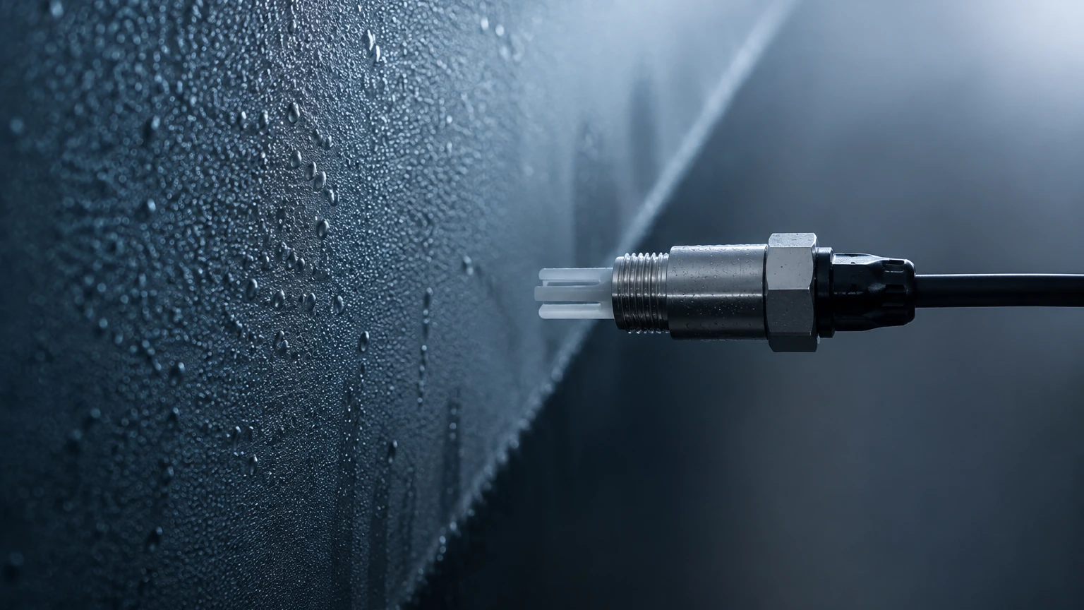
4. Orientation for Condensation: In steam-rich environments, water droplets can form on the sensor face. While 80GHz radar is largely immune to this, mounting the sensor with a slight tilt or using a drip-off lens design helps prevent signal attenuation.
5. Grounding: Ensure that the instrument is properly grounded to the vessel, especially in systems using conductivity or capacitance probes, to prevent electrical noise from interfering with the signal.
Operational Risks and Maintenance
While modern condensate sensors are designed for high reliability, certain risks must be managed through regular maintenance cycles.
* Scaling and Buildup: Over time, minerals in the condensate can form a scale on the sensor probe or diaphragm. This is particularly common in hydrostatic and conductive sensors. Periodic cleaning with appropriate solvents is required.
* Sensor Drift: Thermal cycling (repeated heating and cooling) can cause electronic components to drift. Annual calibration checks against a physical sight glass are recommended.
* Seal Integrity: In high-pressure systems, the primary seal between the process and the sensor electronics is a potential point of failure. Inspect seals for signs of steam leakage or embrittlement.
* Carbonic Acid Corrosion: Condensate can become acidic if carbon dioxide dissolves into it. Ensure that all wetted parts of the condensate sensor are made of corrosion-resistant materials like 316L stainless steel, Hastelloy, or specialized plastics.
Frequently Asked Questions (FAQs)
Q: Can I use an ultrasonic sensor for high-pressure steam condensate?
A: It is generally not recommended. The high-pressure steam changes the density of the air through which the sound travels, significantly affecting the accuracy. Radar is a much more reliable choice for pressurized applications.
Q: What is the benefit of 80GHz radar over 26GHz radar for condensate?
A: 80GHz radar has a much shorter wavelength, allowing for a smaller antenna and a tighter beam angle. This makes it easier to install in small condensate pots and provides better performance when there is condensation on the sensor face.
Q: How do I handle condensate measurement in a vacuum system?
A: Hydrostatic sensors must be of the "differential pressure" type in vacuum systems to account for the pressure above the liquid. Alternatively, radar sensors are excellent in vacuums as electromagnetic waves do not require a medium to travel.
Q: Is a condensate sensor the same as a steam trap monitor?
A: Not necessarily. A steam trap monitor often uses ultrasonic sound or temperature to detect if a trap is leaking steam. A condensate sensor measures the actual liquid level in a collection point or vessel. However, level sensors are often used in "receiver-type" steam traps.
Conclusion
Selecting the right condensate sensor is a balance of understanding the physical properties of the fluid and the mechanical constraints of the process system. For most modern industrial applications, non-contact radar offers the highest reliability and lowest maintenance requirements, particularly in pressurized environments. However, for simple sumps or atmospheric tanks, hydrostatic and ultrasonic technologies remain cost-effective solutions.
By following strict installation guidelines and considering the long-term effects of temperature and scaling, engineers can ensure their condensate management systems operate safely and efficiently. For detailed technical data sheets and to compare different measurement technologies, visiting the Main Page of an established manufacturer like Welk is the recommended next step for procurement and system design.