Hydrocarbon Processing Industry Measuring Instruments
Hydrocarbon Processing Industry Measuring Instruments
In the hydrocarbon processing industry (HPI), which encompasses petroleum refining, gas processing, and petrochemical manufacturing, the accuracy of level measurement is a fundamental requirement for both operational efficiency and plant safety. Hydrocarbon processing industry measuring instruments must withstand extreme temperatures, high pressures, and the presence of corrosive or volatile media. Selecting the correct instrumentation requires a deep understanding of the physical principles governing each technology and how they interact with the unique properties of hydrocarbons.
Whether managing crude oil storage, fractional distillation, or complex chemical synthesis, engineers rely on precise data to prevent tank overfills, optimize throughput, and ensure the integrity of pressure vessels. This guide examines the primary technologies used for level measurement in the HPI, providing technical insights into their principles, applications, and selection criteria.
Principles of Level Measurement in Hydrocarbon Applications
Before selecting a specific instrument, it is essential to understand the underlying measurement principles. In the HPI, these generally fall into two categories: direct (measuring the actual surface position) and indirect (inferring level from pressure or buoyancy).
Radar Level Measurement (Time of Flight)
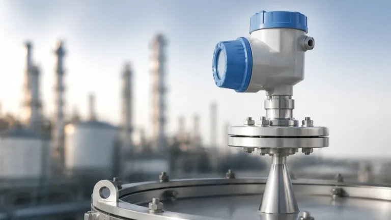
Radar technology is the most prevalent choice for hydrocarbon processing industry measuring instruments due to its non-contact nature and reliability in vacuum or high-pressure environments.
* Non-Contact Radar: These sensors emit high-frequency microwave pulses (often in the 26 GHz or 80 GHz range) toward the liquid surface. The instrument measures the "Time of Flight" (ToF) for the signal to reflect back to the sensor. Because microwaves travel at the speed of light and are largely unaffected by air temperature or vapor space composition, they are ideal for volatile hydrocarbons.
* Guided Wave Radar (GWR): GWR uses a physical probe (rod or cable) to guide the microwave signal to the surface. This is particularly effective for liquids with a low dielectric constant ($ε_r$), such as liquefied petroleum gas (LPG) or light oils. GWR is also the preferred method for interface measurement, such as detecting the boundary between oil and water in a separator.
Ultrasonic Level Measurement
Ultrasonic sensors function similarly to radar but use sound waves instead of electromagnetic waves. A transducer emits an ultrasonic pulse that reflects off the liquid surface. While cost-effective, ultrasonic technology has limitations in the HPI. Sound speed is dependent on the gas composition in the vapor space; in tanks with high concentrations of hydrocarbon vapors or significant temperature gradients, the accuracy can degrade significantly. Consequently, ultrasonic instruments are typically reserved for water treatment or stable chemical storage within the facility.
Hydrostatic Pressure Measurement
This principle relies on the relationship between the height of a liquid column and the pressure it exerts at the base of a vessel. The formula $P = ρ · g · h$ (where $P$ is pressure, $ρ$ is density, $g$ is gravity, and $h$ is height) allows the instrument to calculate the level. In the HPI, hydrostatic transmitters are often used in atmospheric storage tanks. However, because hydrocarbons can change density with temperature, these systems often require temperature compensation to maintain accuracy.
Magnetic Level Gauges (MLG)
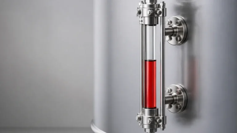
MLGs consist of a bypass chamber attached to the side of a vessel. A float containing a permanent magnet moves up and down with the liquid level, flipping mechanical flags on an external scale. This provides a clear visual indication without requiring power. For electronic integration, a magnetostrictive transmitter can be attached to the chamber to provide a 4-20mA or digital signal.
Technical Selection Matrix
Choosing between different hydrocarbon processing industry measuring instruments requires balancing process conditions against instrument capabilities. The following table provides a general comparison for common HPI scenarios.
| Technology | Typical Accuracy | Max Temperature | Max Pressure | Dielectric Sensitivity | Best Use Case |
| :— | :— | :— | :— | :— | :— |
| Non-Contact Radar | ±1 mm to ±3 mm | Up to +450°C | Up to 160 bar | Low to Moderate | Large storage tanks, reactors |
| Guided Wave Radar | ±2 mm | Up to +400°C | Up to 400 bar | Very High | Interface, small nozzles, LPG |
| Hydrostatic | ±0.1% of span | Up to +200°C | High (depends on sensor) | None | Atmospheric tanks, sumps |
| Magnetic Gauge | ±5 mm (visual) | Up to +400°C | Up to 250 bar | None | High-pressure boilers, toxic media |
| Ultrasonic | ±0.25% of range | Up to +80°C | Up to 3 bar | None | Water basins, non-volatile chemicals |
For engineers seeking specific hardware configurations and detailed technical specifications for these technologies, it is advisable to Review product options and application support to ensure compliance with local safety standards.
Installation Considerations and Best Practices
The performance of hydrocarbon processing industry measuring instruments is often determined by the quality of the installation. In HPI environments, several factors must be addressed during the engineering phase:
1. Nozzle Geometry: For radar and ultrasonic sensors, the diameter and height of the mounting nozzle can interfere with the signal. If a nozzle is too long or narrow, it may create "ringing" or false echoes. High-frequency radar (80 GHz) is more forgiving of narrow nozzles due to its tighter beam angle.
2. Stilling Wells and Bypass Chambers: In vessels with significant turbulence or foam (such as agitators or separators), installing the sensor inside a stilling well or a side-mounted bypass chamber is recommended. This provides a calm surface for measurement and protects the probe from mechanical stress.
3. Hazardous Area Certification: Given the flammable nature of hydrocarbons, instruments must be certified for use in explosive atmospheres (e.g., ATEX, IECEx, or Class/Division systems). This includes the use of explosion-proof housings or intrinsically safe wiring.
4. Vapor Compensation: In high-pressure steam applications or vessels containing heavy hydrocarbon vapors, the dielectric constant of the gas space can change. Advanced radar transmitters include gas phase compensation to correct for the slowing of the microwave signal in these environments.

Limitations and Common Risks
While modern instrumentation is highly advanced, certain HPI conditions pose significant risks to measurement reliability:
* Coating and Buildup: Heavy crude oils, bitumen, and certain polymers can coat the probes of GWR or the faces of ultrasonic transducers. While some radar units feature "signal tracking" software to ignore coating, significant buildup may eventually require physical cleaning or the use of non-contact radar with a PTFE drip shield.
* Low Dielectric Media: Many refined hydrocarbons have a dielectric constant below 2.0. This results in a weak reflection for radar signals. In these cases, GWR with a coaxial probe or the use of a stilling well is necessary to concentrate the signal energy.
* High Turbulence: Rapid filling or vigorous agitation can create surface waves that scatter radar or ultrasonic signals. Using software filters (damping) or mechanical stilling wells can mitigate this effect.
* Temperature Extremes: Cryogenic applications (LNG) or high-temperature refining (coking) require specialized thermal extensions to protect the electronics of the transmitter from the process temperature.
FAQs for HPI Level Instrumentation
Q: Can radar level meters measure the interface between oil and water?
A: Yes, Guided Wave Radar (GWR) is specifically designed for this. A portion of the microwave signal reflects off the upper hydrocarbon layer (low dielectric), while the remainder of the signal continues through the oil and reflects off the water layer (high dielectric).
Q: How does foam affect level measurement?
A: Foam can be problematic. Light, airy foam may be transparent to radar, while dense, thick foam may absorb or reflect the signal prematurely. In foaming applications, low-frequency radar or mechanical solutions like magnetic level gauges are often more reliable.
Q: Is calibration required for radar level meters?
A: Unlike hydrostatic or float-based systems, radar is a "dry" calibration technology. Once the tank geometry and dielectric properties are programmed, the unit rarely requires recalibration unless the process media changes significantly.
Q: What is the benefit of 80 GHz radar over 26 GHz?
A: 80 GHz radar has a much narrower beam angle (as low as 3 degrees). This allows the signal to avoid internal tank obstructions like ladders, heating coils, or agitators, and enables installation in smaller nozzles.
Conclusion and Project Verification
Selecting the right hydrocarbon processing industry measuring instruments is a balance of physics and practical engineering. Before finalizing a specification, project leads should confirm the following data points:
* The minimum and maximum dielectric constant of the media.
* The presence of foam, turbulence, or heavy vapors.
* The exact dimensions of the mounting nozzle.
* The required safety integrity level (SIL) for the loop.
By prioritizing the measurement principle that best suits the physical properties of the hydrocarbon in question, facilities can reduce maintenance costs and improve the safety of their operations. For a comprehensive overview of available technologies and to find a solution tailored to specific industrial requirements, engineers are encouraged to consult the Main Page of the primary technical resource.
Download Hydrocarbon Processing Industry Measuring Instruments as a PDF