Conductive Water Level Sensor
Conductive Water Level Sensor
In the field of industrial process control, the conductive water level sensor remains one of the most reliable and cost-effective methods for point-level detection in conductive liquids. Utilizing the electrical conductivity of the medium itself, these sensors provide a robust solution for monitoring levels in tanks, sumps, and reservoirs. As a professional manufacturer, Welk specializes in providing high-performance level measurement instruments that meet the rigorous demands of water treatment, chemical processing, and industrial automation. For a comprehensive look at the full range of measurement technologies available, engineers often refer to the Main Page of our product catalog to compare conductive probes with radar or ultrasonic alternatives.
Understanding the Measurement Principle
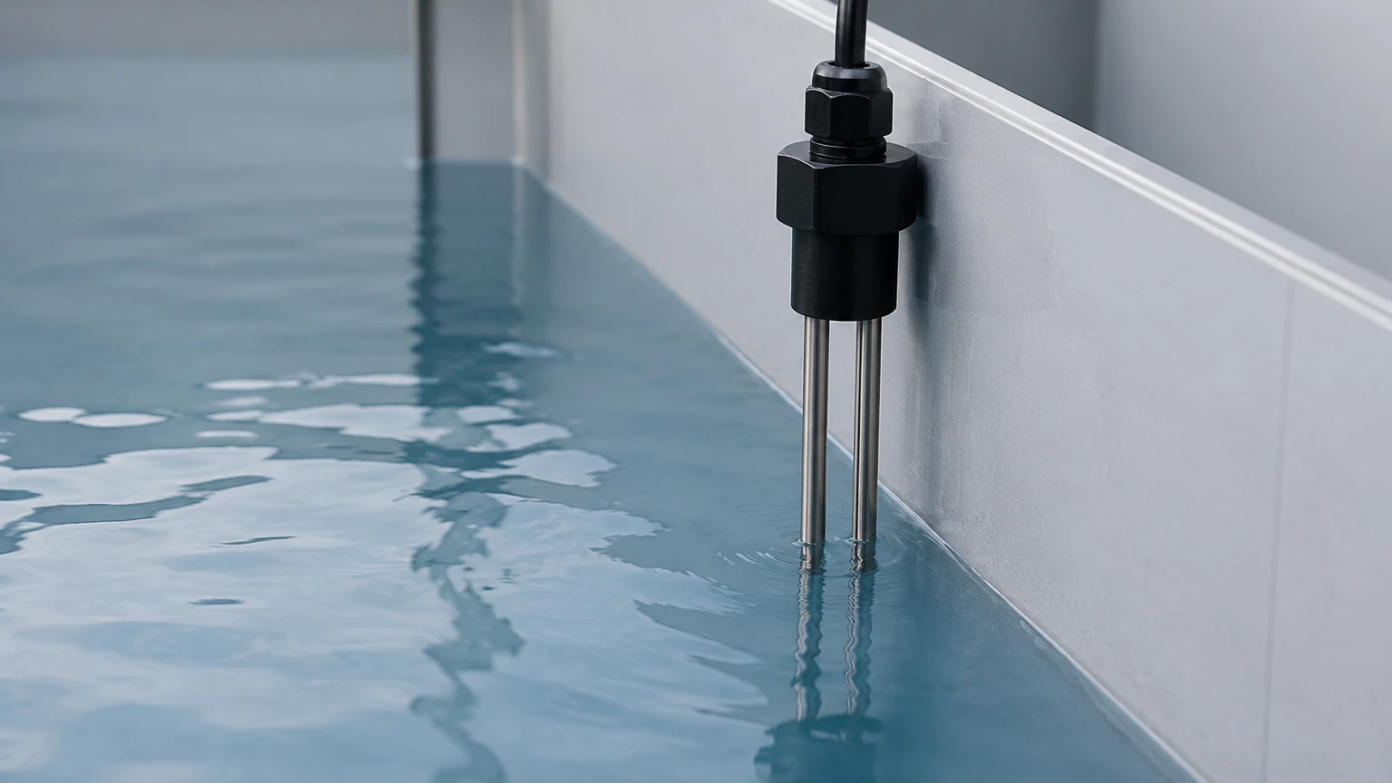
The operation of a conductive water level sensor is based on the principle of electrical resistance. Most water-based liquids, including wastewater, acids, and alkalis, contain ions that allow them to conduct electricity. The sensor system typically consists of a control unit (relay) and a set of electrodes (probes) suspended in the vessel.
The Electrical Circuit
When the liquid level rises and touches the tip of an electrode, an electrical circuit is completed between that electrode and a reference electrode (or the metallic wall of the tank, if grounded). This circuit closure allows a low-voltage current to flow back to the controller. The controller detects this change in resistance and triggers a switching action, such as starting a pump or sounding an alarm.
AC vs. DC Excitation
To prevent the buildup of electrolysis and subsequent corrosion or plating on the electrodes, modern conductive sensors use an Alternating Current (AC) signal rather than Direct Current (DC). DC current would cause ions to migrate permanently to one electrode, leading to rapid degradation of the probe material and false readings. By using AC, the polarity is constantly reversed, maintaining the integrity of the probe surface over long periods of operation.
Technical Selection and Component Materials
Selecting the right conductive water level sensor requires an understanding of both the chemical properties of the liquid and the physical constraints of the installation site. Because the probes are in direct contact with the medium, material compatibility is the primary concern.
Electrode Materials
Probes are available in various alloys to suit different environments:
- Stainless Steel (304/316L): The standard choice for potable water, condensate, and mildly corrosive industrial water.
- Hastelloy C: Used for highly aggressive chemicals where stainless steel would succumb to pitting or general corrosion.
- Titanium: Preferred for seawater applications or specific acidic environments.
Probe Configurations
Sensors are typically categorized by their physical form factor:
1. Rod Probes: Rigid metal rods suited for shorter distances, typically up to 3 meters (9.8 ft). They are ideal for turbulent tanks where a flexible cable might swing.
2. Cable Probes: Suspended by a weighted cable, these are used for deep wells or tall reservoirs where rods would be impractical to transport or install. They can reach depths of 20 meters (65.6 ft) or more.
3. Multi-point Probes: A single head containing multiple electrodes of varying lengths, allowing for high-level, low-level, and common reference points in a single process connection.
Selection Table for Industrial Applications
| Application | Recommended Probe Material | Conductivity Range | Typical Mounting |
| :— | :— | :— | :— |
| Potable Water Storage | SS316L | >20 µS/cm | Top-down Threaded |
| Wastewater Sumps | SS316L with PVC Coating | >50 µS/cm | Bracket / Flange |
| Chemical Batching | Hastelloy C | >10 µS/cm | PTFE Insulated Flange |
| Boiler Level Control | SS316L / Ceramic Insulation | >1 µS/cm | High-pressure NPT |
Installation Considerations and Best Practices
Proper installation is critical to ensure the longevity and accuracy of a conductive water level sensor. Failure to follow engineering best practices often leads to false triggering or premature sensor failure.
Positioning and Clearance
Electrodes should be installed vertically from the top of the tank. A minimum clearance of 50 mm (2 inches) should be maintained between the probes and the tank wall to prevent bridge formation caused by condensation or scaling. If the tank is metallic and used as the reference electrode, the probes must be securely insulated from the tank at the mounting point.
Avoiding Turbulence and Foam
In tanks with high agitation or inflow, the liquid surface may be unstable. Installing the probes inside a stilling well (a pipe that dampens surface movement) can prevent rapid switching of the relay. Additionally, while conductive sensors are generally resistant to foam, extremely thick conductive foam can cause false high-level alarms. In such cases, sensitivity adjustments on the controller are necessary.
Grounding and Reference
For non-metallic tanks (plastic, fiberglass, or concrete), a dedicated reference electrode must be installed. This reference probe must be the longest electrode in the set, ensuring it remains in contact with the liquid even when the other probes are dry. Without a proper reference path, the circuit cannot close, and the sensor will fail to detect the liquid level.
Advantages and Limitations
Every measurement technology has its trade-offs. Understanding where a conductive water level sensor excels and where it struggles is key to successful system design.
Advantages
- Cost-Efficiency: Conductive sensors are significantly less expensive than radar or ultrasonic transmitters, making them ideal for simple point-level tasks.
- No Moving Parts: Unlike float switches, there are no mechanical hinges or pivots to clog or wear out.
- Simplicity: The lack of complex calibration makes them easy for maintenance teams to troubleshoot with a simple multimeter.
- High Pressure/Temperature: With specialized ceramic insulators, these sensors can operate in high-pressure steam boilers where electronic sensors might fail.
Limitations
- Conductivity Requirement: They cannot be used with non-conductive liquids such as oils, hydrocarbons, or pure deionized water (conductivity < 1 µS/cm).
- Coating and Buildup: If the liquid is prone to leaving conductive deposits (like some wastewater or slurries), a bridge may form between electrodes, causing the sensor to stay "on" even when the level has dropped.
- Point Level Only: These sensors provide discrete on/off signals. For continuous 4-20mA level tracking, a different technology must be selected from our Main Page.
Industrial Applications
Water and Wastewater Treatment
In municipal water treatment, conductive probes are used for pump control in lift stations. Their ability to handle the harsh, humid environment of a sewer sump makes them a preferred choice over mechanical floats that can get tangled in debris.
Boiler Feedwater Systems
Steam boilers require precise low-water cutoffs to prevent catastrophic failure. Conductive probes designed for high temperatures (up to 250°C / 482°F) and pressures (up to 40 bar / 580 psi) provide the safety-critical feedback needed to protect the boiler tubes.
Food and Beverage
In the dairy and beverage industry, conductive sensors are used to detect the presence of liquid in pipes to prevent pumps from running dry. Hygienic versions with Tri-clamp fittings and polished stainless steel surfaces ensure compliance with food safety standards.
Maintenance and Troubleshooting FAQ
Q: Why is my sensor indicating a full tank when it is actually empty?
A: This is usually caused by "bridging." Check for moisture, condensation, or material buildup between the probes or inside the connection head. Cleaning the insulators and probes typically resolves the issue. If the liquid leaves a permanent film, consider increasing the distance between probes.
Q: Can I cut the electrode rods to a custom length on-site?
A: Yes, most stainless steel rod electrodes can be cut to the desired length. However, ensure that any protective coating (like PVC or PTFE) is stripped back at the tip by approximately 10-20 mm (0.4-0.8 inches) to allow for electrical contact with the liquid.
Q: How do I test the sensor functionality?
A: With the sensor disconnected from power, you can use a multimeter to check the continuity of the probes. To test the controller, you can momentarily short the probe terminal to the reference terminal with a jumper wire; the relay should click and the indicator LED should change state.
Q: What is the maximum distance between the sensor and the controller?
A: Depending on the sensitivity of the controller and the cable used, the distance can range from 100 meters (328 ft) to 1,000 meters (3,280 ft). Use shielded cable for long runs to prevent electromagnetic interference from nearby power lines.
Conclusion
The conductive water level sensor remains a staple of industrial instrumentation due to its simplicity and reliability. By understanding the electrical properties of the process medium and selecting the appropriate materials and installation methods, engineers can implement a level control solution that requires minimal maintenance over a long service life. For more complex applications requiring non-contact measurement or continuous level data, we invite you to explore our advanced radar and ultrasonic solutions on the Welk Main Page. Our technical team is available to assist with custom OEM/ODM requirements to ensure your specific measurement challenges are met with accuracy and cost-effectiveness.