Controllers for Alarm Starline
Controllers for Alarm Starline
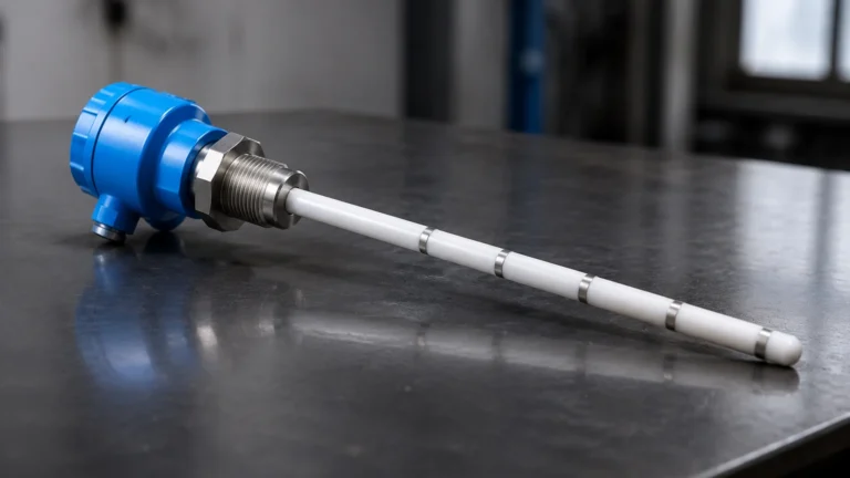
In the field of industrial process control, the reliability of level monitoring is paramount. Magnetic level indicators (MLIs), specifically those within the Starline series and similar bypass configurations, rely on external sensing elements to provide automated feedback. These sensing elements, often referred to as controllers for alarm starline, are critical for preventing tank overfills, protecting pumps from dry running, and maintaining precise inventory levels. As a professional manufacturer, Welk provides advanced solutions for these applications, ensuring that industrial level measurement remains accurate even in the most demanding environments.
Measurement Principles of Magnetic Level Controllers
Before selecting specific controllers for alarm starline, it is essential to understand the underlying physics of magnetic level measurement. This technology is based on the principle of magnetic coupling and buoyancy.
The Magnetic Coupling Effect
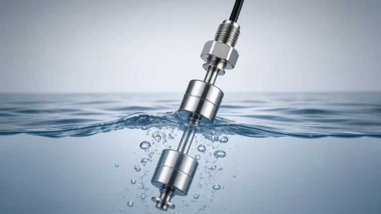
Inside a bypass chamber (a vertical pipe mounted to the side of a vessel), a float is designed to move up and down with the liquid level. This float contains an internal permanent magnet assembly. Outside the chamber, the alarm controller or switch is mounted at a specific set point. Because the chamber is typically constructed from non-magnetic materials like 316 stainless steel or Hastelloy, the magnetic field from the float passes through the chamber wall without interference.
Interaction with the Switch
As the float passes the external controller, the magnetic field interacts with a sensing element—usually a reed switch or a bistable magnetic assembly. This interaction causes the electrical contacts within the controller to change state (from open to closed, or vice versa). This change in state sends a signal to a Control Room, a Programmable Logic Controller (PLC), or a local alarm system. This non-intrusive method ensures that the electrical components never come into contact with the process media, significantly reducing the risk of leaks and corrosion.
Types of Controllers for Starline Level Gauges
There are several technical variations of controllers for alarm starline, each suited to different operational requirements. Choosing the correct type depends on the required signal output and the nature of the process environment.
1. Magnetic Reed Switches
Reed switches consist of two ferromagnetic blades sealed in a glass envelope. When the magnetic float approaches, the blades are drawn together to complete a circuit. These are highly reliable for low-power signal switching and are often used in intrinsically safe circuits. Their hermetically sealed nature makes them ideal for corrosive atmospheres.
2. Bistable (Latching) Switches
In level measurement, a "bistable" function is often required. This means the switch remains in its last state even after the float has moved past it. For example, if the level rises past a high-level alarm point, the switch stays "closed" until the level drops back down past that same point. This prevents the alarm from flickering or resetting prematurely, providing a stable signal for industrial safety systems.
3. High-Temperature Snap-Action Switches
For applications exceeding 250°C (482°F), standard reed switches may fail. High-temperature controllers utilize a mechanical snap-action mechanism triggered by a magnetic linkage. These units often feature cooling fins or stand-off brackets to protect the electrical housing from the radiant heat of the bypass chamber.
4. Continuous Level Transmitters
While technically more than a simple alarm switch, reed-chain transmitters can be mounted alongside Starline gauges to provide a continuous 4-20mA signal. This allows for multiple alarm set points to be programmed digitally within a controller or PLC, offering greater flexibility than fixed-point switches.
Technical Selection Criteria for Alarm Units
When specifying controllers for alarm starline, engineers must evaluate several environmental and process variables to ensure long-term performance.
* Process Temperature: This is the most critical factor. Standard switches typically handle up to 150°C (302°F). For steam applications or high-temperature chemical reactors, specialized high-temp models with heat-dissipating housings are required.
* Housing Material: For offshore or coastal environments, 316 stainless steel housings are preferred over aluminum to prevent salt-spray corrosion. IP66 or IP67 ratings are standard for outdoor installations.
* Electrical Load: It is vital to match the switch contact rating with the input requirements of the control system. Most industrial switches are rated for 1A to 5A at 230VAC/DC, but low-voltage PLC inputs may require gold-plated contacts to ensure signal integrity at low currents.
* Hazardous Area Certification: If the tank contains flammable liquids, the controllers must be certified (e.g., ATEX, IECEx, or UL) as either intrinsically safe (Ex i) or flameproof/explosion-proof (Ex d).
For a comprehensive overview of compatible instrumentation and detailed technical data sheets, professionals should consult the Main Page of our technical resource center.
Installation and Mounting Guidelines
Proper installation is as important as the selection of the hardware itself. Incorrectly mounted controllers for alarm starline can lead to false triggers or complete signal failure.
Positioning the Controller
The switch should be clamped to the outside of the bypass chamber using stainless steel worm gear clamps. The "sensing center" of the switch must align with the desired alarm level. It is important to account for the float's immersion depth; the magnetic center of the float is not always at the liquid surface level, especially in liquids with low specific gravity.
Wiring and Orientation
Most controllers are designed to be mounted vertically. Wiring should include a "drip loop" to prevent moisture from entering the cable gland. In high-vibration environments, ensure that the clamps are tightened to the manufacturer's torque specifications to prevent the switch from sliding down the chamber over time.
Calibration and Testing
Before commissioning, a "dry test" should be performed. This involves manually moving a magnet (or the float itself, if the chamber is empty) past the switch to verify that the control room receives the correct signal. This confirms both the mechanical operation of the switch and the integrity of the electrical loop.

Selection Table for Level Alarm Controllers
The following table provides a general comparison of common controller configurations used with Starline-style magnetic level indicators.
| Controller Model | Switch Type | Max. Temperature | Enclosure Rating | Typical Application |
| :— | :— | :— | :— | :— |
| Standard Reed | Bistable Reed | 150°C (302°F) | IP65 / NEMA 4 | General water/oil storage |
| High-Temp Snap | Snap-Action | 400°C (752°F) | IP66 / NEMA 4X | Boiler drums, thermal oil |
| Ex-Proof Series | Hermetic Reed | 200°C (392°F) | Ex d IIC T6 | Oil & Gas, Refineries |
| Low-Current | Gold Contact | 120°C (248°F) | IP67 | PLC/DCS direct interface |
*Note: All temperature ratings refer to the process temperature at the chamber wall. Ambient temperature limits for the housing typically range from -40°C to +80°C.*
Operational Limitations and Maintenance
While controllers for alarm starline are designed for low maintenance, certain limitations must be acknowledged to prevent system failures.
1. Magnetic Interference: Large motors, high-voltage cables, or nearby ferrous structures can interfere with the magnetic coupling. A minimum clearance of 100mm (approx. 4 inches) from other magnetic sources is generally recommended.
2. Particle Accumulation: In processes with magnetic particles (e.g., iron filings in lubricating oil), these particles can cling to the internal float, changing its buoyancy or interfering with the magnetic field. Magnetic filters or traps should be installed in the bypass piping in such cases.
3. Contact Wear: Although reed switches are rated for millions of cycles, switching inductive loads (like large relays or solenoid valves) without proper arc suppression (diodes or RC snubbers) can cause the contacts to weld together.
Regular maintenance should include a visual inspection of the housing for moisture ingress and a functional test of the alarm trip points during scheduled plant shutdowns.
Frequently Asked Questions (FAQs)
Q: Can I use these controllers on non-Welk bypass gauges?
A: Yes, most controllers for alarm starline are designed with universal mounting clamps that allow them to be attached to any non-magnetic bypass chamber with an outer diameter typically ranging from 50mm to 75mm (2" to 3").
Q: What is the difference between an SPDT and DPDT switch in this context?
A: An SPDT (Single Pole Double Throw) switch provides one set of contacts (one normally open, one normally closed). A DPDT (Double Pole Double Throw) provides two independent sets of contacts, allowing you to trigger two separate circuits (e.g., a local siren and a remote PLC signal) from a single alarm unit.
Q: How do I handle very low-density liquids?
A: For low-density liquids (Specific Gravity < 0.5), the float must be larger and the magnets more powerful. Ensure the controller is sensitive enough to detect the magnetic field through the potentially thicker chamber walls required for high-pressure, low-density applications.
Q: Are there wireless options for these alarm controllers?
A: While most industrial controllers are hard-wired for safety and reliability, WirelessHART or LoRaWAN adapters can be integrated with the switch output to transmit alarm states in remote locations where cabling is cost-prohibitive.
For further engineering support regarding level measurement and control, please refer to the technical documentation available on our Main Page. Our team at Welk is dedicated to providing robust, accurate, and cost-effective solutions for global industrial automation.