Coriolis Flow Transmitter
Coriolis Flow Transmitter
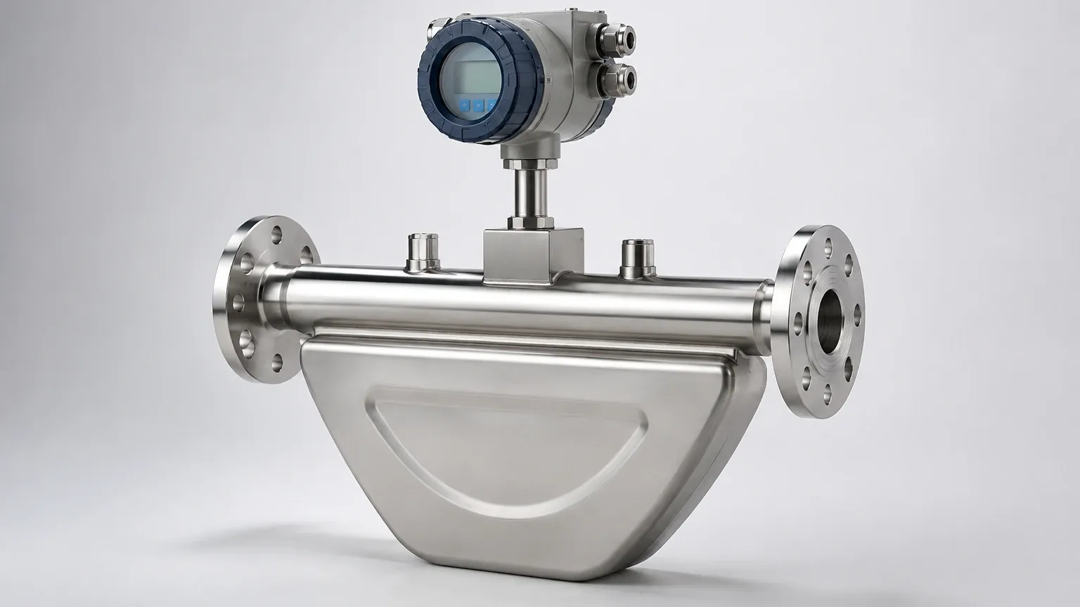
In the landscape of industrial process control, the Coriolis flow transmitter stands as one of the most versatile and accurate instruments available for fluid measurement. Unlike volumetric flow meters that measure the space a fluid occupies, a Coriolis flow transmitter measures mass directly. This distinction is critical in industries where temperature and pressure fluctuations can alter fluid density, rendering volumetric readings inconsistent. By providing direct mass flow, density, and temperature data in a single device, these transmitters have become the gold standard for high-precision applications in chemical processing, oil and gas, and food production.
Measurement Principles of Coriolis Technology
To understand the function of a Coriolis flow transmitter, one must first examine the physical phenomenon known as the Coriolis effect. In an industrial meter, this principle is applied by inducing a controlled vibration into one or two measuring tubes through which the process fluid flows.
The Coriolis Effect in Practice
When the fluid is at rest and the tubes are vibrating, the inlet and outlet sections of the tube move in unison. However, when fluid begins to flow, the mass of the moving fluid generates an inertia that resists the vibrational movement. This results in a "twist" or a phase shift in the tube’s oscillation.
1. Oscillation: An internal drive coil causes the measuring tubes to vibrate at their resonant frequency.
2. Phase Shift: Electromagnetic pick-off sensors located at the inlet and outlet sides of the tubes detect the vibration. As fluid flows, the inlet side of the tube lags behind the drive vibration, while the outlet side leads it.
3. Mass Calculation: The time difference (delta-T) between the signals from the two pick-off sensors is directly proportional to the mass flow rate.
4. Density Measurement: The resonant frequency at which the tubes vibrate changes based on the mass of the fluid inside them. A denser fluid increases the total mass of the system, lowering the frequency. By measuring this frequency, the transmitter calculates the fluid's density.
This multi-variable capability allows the transmitter to output mass flow, volume flow, density, and temperature simultaneously, providing a comprehensive view of the process state. For engineers looking to integrate these data points into broader automation systems, reviewing modern Main Page options for compatible instrumentation is a standard step in system design.
Key Evaluation Criteria for Selection
Selecting the correct Coriolis flow transmitter requires a detailed analysis of the process fluid and the mechanical constraints of the installation site. Because these instruments are a significant capital investment, the following criteria must be confirmed:
Accuracy and Turndown Ratio
Coriolis meters typically offer accuracy levels between 0.1% and 0.05% for liquids. The turndown ratio—the range over which the meter maintains its stated accuracy—is also exceptionally high, often exceeding 100:1. Engineers should evaluate whether the process requires high-end precision or if a standard industrial grade is sufficient.
Material Compatibility
The measuring tubes are the most critical component. They are typically constructed from 316L stainless steel, but for corrosive media, alloys such as Hastelloy C-22 or Tantalum may be required. The transmitter housing should also be rated for the environment, particularly in offshore or chemical plant settings where salt spray or acidic vapors are present.
Pressure Drop
Because the fluid must pass through the geometry of the measuring tubes (which may involve a split flow or a curved path), a pressure drop is inevitable. This must be calculated to ensure the pump capacity is sufficient to maintain required flow rates at the point of delivery.
Practical Selection Table
| Parameter | Requirement | Considerations |
| :— | :— | :— |
| Fluid State | Liquid, Slurry, or Gas | High-viscosity fluids and slurries require larger tube diameters. |
| Flow Rate Range | 10 kg/h to 500,000 kg/h | Select a meter size where the nominal flow is 50-70% of the maximum capacity. |
| Operating Pressure | Up to 350 bar (5,076 psi) | Ensure the tube wall thickness is rated for the maximum system pressure. |
| Temperature Range | -200°C to +350°C | Cryogenic or high-temp applications require specialized remote electronics. |
| Required Outputs | 4-20mA, HART, Modbus | Digital protocols are preferred for multi-variable data transmission. |
Installation Considerations
While Coriolis flow transmitters are less sensitive to flow profiles than ultrasonic or magnetic meters, they are highly sensitive to mechanical vibration and mounting stresses. Proper installation is paramount to maintaining the instrument's calibrated accuracy.
1. Vibration Isolation: The meter should not be installed near heavy machinery, pumps, or motors that generate significant vibration. If vibration is unavoidable, flexible connectors or specialized damping mounts should be used.
2. Orientation: For liquid applications, the tubes should ideally point downward (U-shape) to prevent gas bubbles from becoming trapped. For gas applications, the tubes should point upward to prevent condensate from collecting in the sensor.
3. Mechanical Stress: The piping must be properly supported so that the weight of the pipe does not pull or push on the meter flanges. Misalignment can cause a "zero-shift," where the meter reports flow even when the fluid is stationary.
4. Entrained Air: Even small amounts of air in a liquid stream can cause the tubes to vibrate erratically, leading to "slug flow" errors. Air eliminators should be installed upstream if the process is prone to aeration.
Limitations and Common Risks
Despite their advanced capabilities, Coriolis flow transmitters are not universal solutions. Understanding their limitations prevents costly misapplications.
* Initial Cost: The acquisition cost of a Coriolis meter is significantly higher than that of a turbine or differential pressure meter. The ROI must be justified by the need for mass flow accuracy or density data.
* Size and Weight: High-capacity Coriolis meters are bulky and heavy. This may require additional structural support for the piping system.
* Gas Measurement Challenges: While capable of measuring gas, the low density of gases results in a very small Coriolis force. This often necessitates higher flow velocities and leads to a higher pressure drop compared to liquid measurement.
* Zero Stability: Over time, or due to extreme temperature cycles, the "zero point" of the meter may drift. Regular zero-verification under no-flow conditions is required to maintain accuracy.
Frequently Asked Questions (FAQs)
Q: Does a Coriolis flow transmitter require straight pipe runs?
A: Generally, no. Unlike many other technologies, Coriolis meters are mostly immune to turbulence and do not require long straight runs of pipe upstream or downstream. However, they should still be installed away from valves that may cause cavitation.
Q: Can it measure the flow of non-conductive liquids?
A: Yes. Unlike electromagnetic flow meters, the Coriolis principle does not rely on electrical conductivity. It works equally well on deionized water, hydrocarbons, and oils.
Q: How does the transmitter handle varying viscosities?
A: The Coriolis effect is independent of viscosity. However, high-viscosity fluids will result in a higher pressure drop across the meter, which must be accounted for during the sizing process.
Q: Is periodic recalibration necessary?
A: While the sensor has no moving parts to wear out, the electronics and the mechanical integrity of the tubes can be affected by extreme conditions. Annual verification is recommended, though many modern transmitters include internal diagnostic suites that monitor the health of the tubes (Meter Verification).
Integration with Industrial Systems
In modern B2B environments, the Coriolis flow transmitter is rarely a standalone device. It is typically integrated into a larger control architecture. For instance, in chemical batching, the mass flow data from the transmitter is used in conjunction with level measurement instruments to ensure the correct mass-balance of a reactor. When designing such systems, sourcing reliable instruments from a Main Page that understands industrial automation ensures that the flow data integrates seamlessly with PLC and SCADA systems.
By focusing on the fundamental physics of the Coriolis effect and adhering to strict installation guidelines, engineering teams can leverage these transmitters to achieve unparalleled process transparency and efficiency. Whether managing expensive raw materials or ensuring the safety of high-pressure chemical reactions, the Coriolis flow transmitter remains a cornerstone of precision instrumentation.