Coriolis Mass Flow Meter Principle
Coriolis Mass Flow Meter Principle
In the realm of industrial process control, the ability to measure the mass of a fluid directly—rather than its volume—provides a significant advantage in accuracy and process stability. While volumetric flow meters are common, they are susceptible to errors caused by changes in temperature, pressure, and fluid density. The Coriolis mass flow meter overcomes these variables by utilizing a fundamental law of physics. This article provides a comprehensive technical overview of the Coriolis mass flow meter principle, its mechanical design, and practical considerations for its application in modern industrial environments.
Understanding the Fundamental Coriolis Effect
To understand the Coriolis mass flow meter principle, one must first understand the Coriolis effect. Named after the French physicist Gaspard-Gustave de Coriolis, this effect describes the inertial force that acts on objects in motion within a frame of reference that rotates.
A classic analogy is a person standing on a rotating merry-go-round. If that person attempts to walk in a straight line from the center to the edge, they will feel a force pushing them sideways. This is because the linear velocity of the platform increases as they move further from the center (since the outer edge covers more distance per revolution than the center). The resistance to this change in velocity manifests as the Coriolis force.
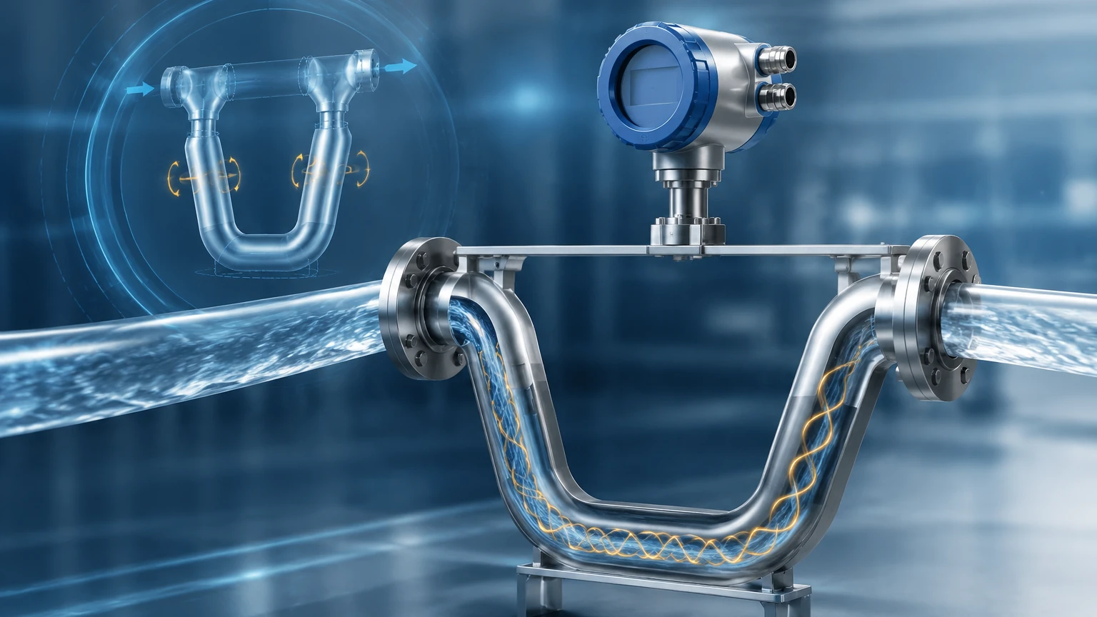
In an industrial flow meter, this rotation is not continuous but is instead simulated by vibrating a flow tube at its resonant frequency. When a fluid (liquid or gas) flows through this vibrating tube, it is subjected to Coriolis forces, which cause the tube to distort or "twist."
The Coriolis Mass Flow Meter Principle in Detail
The measurement process within a Coriolis meter involves several integrated physical phenomena: vibration, phase shift, and frequency analysis.
1. Tube Vibration and Drive System
Most Coriolis meters consist of one or two flow tubes. An electromagnetic drive coil (similar to a loudspeaker magnet) is used to vibrate the tubes at their natural resonant frequency. In a dual-tube design, the tubes vibrate in opposition to each other, acting like a tuning fork. This balanced design minimizes the influence of external pipeline vibrations on the measurement.
2. The Generation of Coriolis Force
As fluid enters the vibrating tube, it is forced to take on the vertical velocity of the vibration. On the inlet side of the tube, the fluid is moving toward the center of the vibration (the point of maximum displacement), resisting the upward motion and pushing down on the tube. On the outlet side, the fluid is moving away from the center of vibration, resisting the downward pull and pushing up on the tube.
3. Measuring Phase Shift
This opposing force on the inlet and outlet sides causes the flow tube to twist. Precision sensors, often called "pick-offs," are located at the inlet and outlet sections of the tube to monitor the vibration.
* Zero Flow: When there is no fluid moving, the tube vibrates uniformly. The sine waves generated by the inlet and outlet pick-offs are in phase (they peak at the exact same time).
* With Flow: When fluid moves through the tube, the Coriolis-induced twist causes the inlet side to lag behind the outlet side. This results in a time delay, or "phase shift," between the two sine waves.
The mass flow rate is directly proportional to this phase shift. Because the measurement is based on inertia and mass, it is independent of the fluid’s viscosity, conductivity, or flow profile.
4. Density and Temperature Measurement
Beyond mass flow, Coriolis meters are multi-variable instruments. They measure fluid density by monitoring the resonant frequency of the vibrating tube. A heavier fluid (higher density) increases the mass of the vibrating system, which lowers the resonant frequency. Conversely, a lighter fluid allows the tube to vibrate at a higher frequency.
Furthermore, because the elasticity of the flow tube changes with temperature, a built-in Resistance Temperature Detector (RTD) monitors the tube temperature. This data is used to compensate for thermal effects on the tube's stiffness and provides an accurate process temperature output to the user.
Design Variations: Curved vs. Straight Tubes
Engineers must choose between different tube geometries based on the specific requirements of their application.
| Feature | Curved (U-Shape) Tubes | Straight Tubes |
| :— | :— | :— |
| Sensitivity | Extremely high; ideal for low flow rates. | Lower; requires more robust electronics. |
| Pressure Drop | Generally higher due to the bends. | Minimal; similar to a straight pipe. |
| Cleanability | Harder to drain; risk of fluid entrapment. | Excellent; ideal for food and pharma (CIP/SIP). |
| Compactness | Requires more vertical or horizontal space. | Compact; easier to install in tight runs. |
| Stress Tolerance | Better at handling thermal expansion. | May require bellows or specific mounting to handle stress. |
Practical Selection Criteria
When evaluating a Coriolis meter for a project, several technical factors must be confirmed to ensure long-term reliability and accuracy.
1. Mass Flow Range: Ensure the meter’s "sweet spot" for accuracy aligns with your nominal flow rate. While Coriolis meters have high turndown ratios (often 100:1), accuracy degrades at the very bottom of the range.
2. Material Compatibility: The wetted parts (usually 316L Stainless Steel, Hastelloy C-22, or Tantalum) must be chemically compatible with the process fluid to prevent corrosion or erosion.
3. Pressure Rating: The wall thickness of the flow tubes dictates the maximum operating pressure. Thicker tubes handle higher pressure but may reduce the sensitivity of the mass flow measurement.
4. Gas Entrainment: Coriolis meters perform best with single-phase fluids. If a liquid contains entrained gas (bubbles), it can dampen the tube vibration and lead to "slug flow" errors. Advanced digital signal processing (DSP) in modern meters helps mitigate this, but it remains a limitation.
Installation Considerations and Best Practices
Proper installation is critical to maintaining the high accuracy (typically ±0.1% to ±0.05%) associated with the Coriolis mass flow meter principle.
* Vibration Isolation: Although dual-tube designs are balanced, high-frequency vibration from nearby pumps or valves can interfere with the meter's drive frequency. Using flexible connectors or robust piping supports is recommended.
* Orientation:
* Liquids: The meter should be installed with the tubes pointing downward (in a "flag" or "U" position) to ensure they remain full and to prevent gas bubbles from being trapped.
* Gases: The meter should be installed with the tubes pointing upward to allow any condensed liquids to drain out.
* Zero Calibration: After installation and under full-pipe, zero-flow conditions, a "zero trim" must be performed. This accounts for the specific mechanical stresses of the piping on the meter body.
* Avoid Cavitation: Ensure the downstream pressure is high enough to prevent the fluid from flashing or cavitating inside the meter tubes, which will cause erratic readings.
Limitations of Coriolis Technology
While highly accurate, Coriolis meters are not a universal solution for every application.
* Initial Cost: They are significantly more expensive than electromagnetic or ultrasonic flow meters, especially in larger line sizes (above 200 mm / 8 inches).
* Size and Weight: Large Coriolis meters are heavy and require substantial structural support.
* Pressure Loss: In high-viscosity applications, the pressure drop across a curved-tube Coriolis meter can be substantial, potentially requiring larger pumps.
Comparison with Other Flow Technologies
To provide context within a broader industrial instrumentation strategy, it is helpful to compare Coriolis meters with other common technologies used alongside Main Page solutions.
| Technology | Measurement Type | Accuracy (Typical) | Maintenance | Primary Advantage |
| :— | :— | :— | :— | :— |
| Coriolis | Direct Mass | ±0.1% | Low (No moving parts) | Multi-variable (Mass, Density, Temp) |
| Electromagnetic | Volumetric | ±0.5% | Low | No pressure drop; handles slurries |
| Vortex | Volumetric | ±1.0% | Medium | Good for steam and high temps |
| Differential Pressure | Inferential | ±1.0% – 2.0% | High (Impulse lines) | Well-understood; low cost |
Frequently Asked Questions (FAQs)
Q: Can Coriolis meters measure the flow of non-conductive liquids?
A: Yes. Unlike electromagnetic flow meters, the Coriolis principle does not rely on electrical conductivity. It works equally well on deionized water, hydrocarbons, and oils.
Q: How does the meter handle changing viscosities?
A: The Coriolis force is independent of viscosity. However, very high viscosity fluids will result in a higher pressure drop across the meter. The mass flow accuracy remains unaffected.
Q: Is straight pipe run required before and after the meter?
A: Generally, no. Unlike turbine or orifice plate meters that require long straight runs to stabilize the flow profile, Coriolis meters are largely immune to flow profile disturbances. However, it is still good practice to avoid placing valves or elbows immediately upstream if possible.
Q: Can it measure bi-directional flow?
A: Yes, Coriolis meters are inherently bi-directional. The phase shift will simply reverse direction, allowing the electronics to indicate negative flow.
Conclusion
The Coriolis mass flow meter principle represents one of the most reliable methods for achieving precision in fluid processing. By measuring mass directly and providing real-time density and temperature data, these instruments allow for tighter process control, reduced waste, and improved product consistency. While the initial investment is higher than volumetric alternatives, the reduction in calibration requirements and the elimination of pressure/temperature compensation often result in a lower total cost of ownership.
For engineers integrating these systems into larger automation frameworks, understanding the mechanical boundaries and installation requirements is essential. Whether managing chemical dosing or oil and gas custody transfer, the Coriolis meter stands as a cornerstone of modern industrial measurement. For more information on complementary measurement technologies, including radar and ultrasonic systems, you may review product options and application support on our Main Page.