Coriolis Mass Flow Transmitter
Coriolis Mass Flow Transmitter
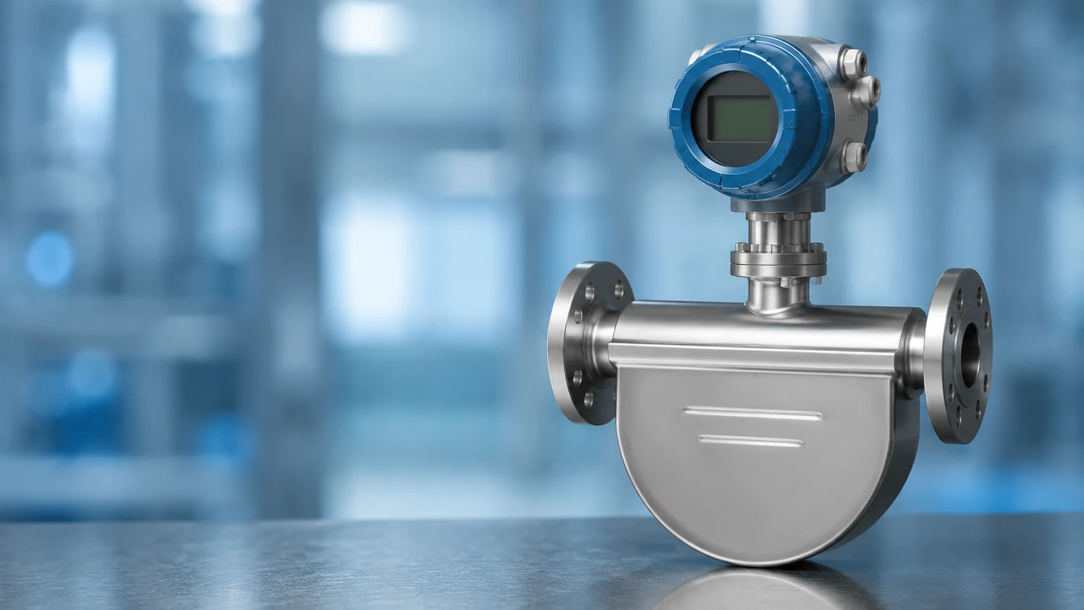
In the landscape of industrial process control, the Coriolis mass flow transmitter represents one of the most accurate and versatile instruments available for fluid measurement. Unlike volumetric flow meters, which measure the space a fluid occupies, a Coriolis transmitter measures the actual mass of the fluid passing through the system. This distinction is critical in industries where temperature and pressure fluctuations can alter fluid density, rendering volumetric readings unreliable for precise inventory control or chemical dosing.
As process industries move toward higher automation and stricter quality standards, understanding the engineering principles, selection criteria, and installation nuances of Coriolis technology is essential for plant engineers and system integrators. This guide provides a technical overview of how these devices function and how to implement them effectively within a broader instrumentation framework, such as those found on the Main Page of industrial measurement catalogs.
Measurement Principles of Coriolis Technology
The operation of a Coriolis mass flow transmitter is based on the principles of classical mechanics, specifically the Coriolis effect. This effect describes the inertial force acting on an object that moves within a rotating frame of reference. In an industrial flow meter, this rotation is simulated by vibrating the internal flow tubes.
The Coriolis Effect in Flow Tubes
Inside the meter, one or two flow tubes are driven to vibrate at their resonant frequency by an electromagnetic drive coil. When there is no flow, the tubes vibrate uniformly. However, when a fluid (liquid or gas) enters the vibrating tubes, it is forced to take on the vertical momentum of the vibrating tube.
As the fluid moves toward the center of the vibration (the peak of the oscillation), it resists being pushed upward, exerting a force against the tube. Conversely, as the fluid moves away from the center toward the outlet, it resists the slowing of its vertical motion, exerting a force in the opposite direction. This results in a "twisting" or phase shift in the tube's vibration.
Mass Flow Calculation
The amount of twist or phase shift between the inlet and outlet sides of the tube is directly proportional to the mass flow rate. Highly sensitive pick-off coils located on both sides of the tube detect this phase difference (measured in microseconds). The transmitter then processes this time delay ($Δt$) to calculate the mass flow using the formula:
ṁ = FC · (Δt – Δt₀)
Where:
* ṁ: Mass flow rate
* FC: Flow calibration factor (determined by the manufacturer)
* Δt: Measured time delay
* Δt₀: Time delay at zero flow (zero offset)
Simultaneous Density and Temperature Measurement
One of the primary advantages of a Coriolis mass flow transmitter is its ability to measure multiple parameters simultaneously:
1. Mass Flow: Derived from the phase shift.
2. Density: Derived from the resonant frequency of the tubes. A denser fluid increases the mass of the tube system, lowering the vibration frequency. This allows for real-time concentration monitoring (e.g., Brix or Plato scales).
3. Temperature: Measured via an internal RTD (Resistance Temperature Detector) to compensate for changes in tube elasticity caused by thermal fluctuations.
Selection Criteria for Coriolis Transmitters
Selecting the appropriate Coriolis meter requires a balance between accuracy requirements, fluid properties, and budget constraints. Engineers must evaluate the physical design of the tubes and the capabilities of the transmitter electronics.
Tube Geometry: U-Shape vs. Straight Tube
| Feature | U-Shaped Tubes | Straight Tubes |
| :— | :— | :— |
| Sensitivity | High sensitivity to low flow rates due to larger phase shifts. | Lower sensitivity; requires higher velocities for accuracy. |
| Pressure Drop | Higher pressure drop due to the curved path. | Minimal pressure drop; ideal for viscous fluids. |
| Cleanability | Harder to drain; may trap solids or air. | Excellent; self-draining and piggable (CIP/SIP friendly). |
| Installation | Requires more space; sensitive to external vibration. | Compact; easier to fit into tight piping runs. |
| Material Stress | Higher mechanical stress at the bends. | Lower stress; generally more robust against thermal shock. |
| Metric/Imperial | Available in DN15 to DN300 (1/2" to 12"). | Available in DN15 to DN100 (1/2" to 4"). |
Material Compatibility
The wetted parts of the transmitter must be compatible with the process fluid. Common materials include:
* 316L Stainless Steel: The standard for most industrial applications and water treatment.
* Hastelloy C-22: Used for highly corrosive chemicals like hydrochloric acid.
* Tantalum: Reserved for extreme chemical resistance requirements.
Installation Considerations and Best Practices
Even the most accurate Coriolis mass flow transmitter will provide erroneous data if installed incorrectly. Because the device relies on subtle vibrations, mechanical isolation and proper orientation are paramount.
1. Orientation for Fluid Phases
* Liquids: The meter should ideally be installed in a "flag" position (vertical flow upward) or with the tubes pointing downward in a horizontal run. This ensures the tubes remain full and prevents air bubbles from becoming trapped, which can dampen the vibration.
* Gases: For gas measurement, the tubes should point upward in a horizontal installation. This allows any condensed liquids to drain out of the tubes, preventing measurement errors caused by "slugging."
2. Vibration Isolation
Coriolis meters are sensitive to external mechanical noise. They should be mounted on rigid, vibration-free supports. It is recommended to use flexible couplings if the surrounding piping is subject to significant vibration from pumps or compressors. However, the meter itself must be securely anchored to a solid structure.
3. Zeroing the Meter
After installation and once the meter is filled with the process fluid at operating temperature and pressure, a "zero calibration" must be performed. This involves closing valves on both sides of the meter to ensure a state of absolute zero flow. The transmitter then records the residual phase shift (Δt₀) and uses it as a baseline for all subsequent measurements.
4. Avoiding Cavitation and Flashing
To maintain accuracy, the fluid must remain in a single phase. Pressure at the meter outlet must be kept high enough to prevent cavitation (liquid turning to vapor). A common rule of thumb is to maintain a backpressure at least twice the pressure drop across the meter plus 1.25 times the vapor pressure of the liquid.
Limitations and Practical Challenges
While highly versatile, Coriolis mass flow transmitters are not a universal solution for every application. Engineers should be aware of the following limitations:
* Initial Cost: Coriolis meters are significantly more expensive than electromagnetic or vortex flow meters. The ROI is typically found in applications where accuracy (often 0.1% or better) is vital for cost-savings or safety.
* Size and Weight: Large-diameter Coriolis meters (above DN200 or 8 inches) are extremely heavy and bulky, often requiring dedicated structural supports.
* Entrained Gas: Small amounts of gas in a liquid stream (and vice versa) can cause the tubes to vibrate erratically, leading to "stalling" or significant measurement errors. Advanced digital signal processing (DSP) in modern transmitters has mitigated this, but it remains a concern for high-viscosity fluids.
* Pressure Rating: Because the flow tubes must be thin enough to vibrate, they often have lower pressure ratings than the surrounding heavy-walled piping.
Integration with Level Measurement Systems
In many B2B industrial environments, mass flow transmitters work in tandem with level measurement instruments. While a Coriolis meter tracks the movement of material into a vessel, radar or ultrasonic level sensors—such as those manufactured by Welk—provide the final verification of inventory.
For example, in a chemical blending tank, a Coriolis transmitter ensures the precise mass of a reactant is added, while a hydrostatic level transmitter monitors the total volume to prevent overfills. This multi-layered approach to process monitoring ensures both accuracy in the recipe and safety in operations. For more information on how flow and level instruments integrate into a complete automation strategy, you can review product options and application support on the Main Page.
Frequently Asked Questions (FAQ)
Q: How often does a Coriolis mass flow transmitter need to be recalibrated?
A: Because there are no moving parts subject to wear (like bearings in a turbine meter), Coriolis meters are exceptionally stable. Many facilities perform a "dry" verification of the electronics annually and a full wet calibration every 3 to 5 years, depending on the criticality of the process and local regulations.
Q: Can a Coriolis meter measure the flow of non-conductive liquids?
A: Yes. Unlike electromagnetic flow meters, which require a minimum fluid conductivity, Coriolis meters are unaffected by the electrical properties of the fluid. They work equally well with deionized water, hydrocarbons, and liquid gases.
Q: What is the typical turndown ratio for a Coriolis transmitter?
A: Most high-quality Coriolis transmitters offer a turndown ratio of at least 20:1, with many reaching 100:1 while maintaining acceptable accuracy. This makes them ideal for processes with wide variations in flow rates.
Q: Does viscosity affect the accuracy of the measurement?
A: Mass flow measurement is largely independent of viscosity. However, highly viscous fluids will result in a higher pressure drop across the meter, which may necessitate a larger meter size or a straight-tube design to maintain flow rates.
Conclusion
The Coriolis mass flow transmitter remains the gold standard for precision fluid measurement in the chemical, oil and gas, and food processing sectors. By measuring mass directly and providing secondary data on density and temperature, it offers a level of process insight that volumetric meters cannot match. When properly selected based on tube geometry and material compatibility, and installed with attention to mechanical isolation, these instruments provide a reliable foundation for sophisticated industrial automation and inventory management.