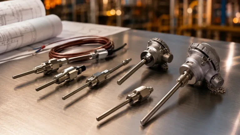
Cpa Flow Conditioner
Cpa Flow Conditioner
In industrial fluid dynamics, the accuracy of measurement instruments is heavily dependent on the state of the fluid as it passes through the sensor. Whether measuring flow rates or monitoring liquid levels in high-velocity systems, turbulence and swirl can introduce significant errors. The cpa flow conditioner is a high-performance solution designed to rectify these disturbances, ensuring that measurement devices operate within their specified accuracy tolerances.
For engineers managing complex piping networks in water treatment, chemical processing, or oil and gas, understanding the integration of flow conditioning is essential. While level measurement instruments—such as those found on the Main Page of industrial catalogs—focus on vertical displacement, the stability of the liquid surface and the precision of inflow data often rely on the performance of upstream flow conditioners.
Measurement Principles and Flow Dynamics
To understand why a cpa flow conditioner is necessary, one must first examine the behavior of fluid within a pipe. In an ideal scenario, fluid moves in a "fully developed flow profile," where the velocity is highest at the center and decreases toward the pipe walls in a predictable, symmetrical curve. However, real-world piping configurations rarely allow for this.
Swirl and Velocity Profile Distortion
When fluid passes through elbows, T-junctions, valves, or pumps, two primary types of disturbances occur:
1. Swirl: The fluid begins to rotate around the longitudinal axis of the pipe. This is common after two out-of-plane elbows.
2. Profile Distortion: The velocity profile becomes asymmetrical, with the highest velocity shifted toward one side of the pipe.
Most measurement technologies, particularly ultrasonic and orifice meters, assume a symmetrical flow profile. Swirl can cause an ultrasonic meter to miscalculate the travel time of signals, while profile distortion can lead to incorrect differential pressure readings in orifice plates. A cpa flow conditioner works by forcing the fluid through a series of engineered apertures that break up large vortices and redistribute the velocity evenly across the pipe's cross-section.
The CPA Design Mechanism
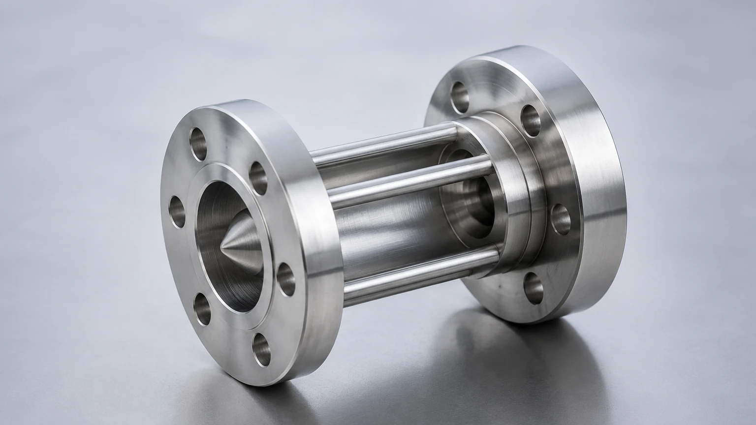
The "CPA" (Canada Pipeline Accessories) style conditioner typically utilizes a perforated plate design with a specific hole pattern. Unlike simple straightening vanes, which only address swirl, the CPA pattern is designed to address both swirl and profile distortion simultaneously. By creating a controlled pressure drop, the plate forces the fluid to reorganize into a predictable profile over a much shorter distance than natural pipe friction would allow.
Technical Specifications and Selection Criteria
Selecting the correct cpa flow conditioner requires an analysis of the process conditions, pipe geometry, and the specific requirements of the primary measurement element. The following table outlines the standard selection parameters for industrial applications.
Selection Table: CPA Flow Conditioner Parameters
| Feature | Specification Details |
| :— | :— |
| Standard Pipe Sizes | DN50 (2") to DN1200 (48") |
| Material Options | 304/316L Stainless Steel, Carbon Steel, Duplex Steel |
| Pressure Ratings | ASME Class 150 to Class 2500 |
| Typical Thickness | 12.7 mm (0.5") to 50 mm (2") depending on pipe diameter |
| Hole Pattern | CPA 50E or proprietary high-performance patterns |
| Mounting Style | Flange-mounted (raised face or ring-type joint) |
Pressure Drop Considerations
A critical factor in selection is the permanent pressure loss (PPL) introduced by the conditioner. Because the device restricts the flow path to reshape the profile, it inevitably consumes some energy. In gravity-fed systems or low-pressure water treatment lines, this pressure drop must be calculated to ensure it does not interfere with the overall system hydraulics or the minimum head requirements for downstream level sensors.
Integration with Level Measurement Systems
While flow conditioners are primarily associated with flow meters, they play a supporting role in advanced level measurement strategies. In many industrial automation setups, flow and level data are cross-referenced to perform mass balance calculations or to detect leaks.
Stilling Wells and Bypass Chambers
In tanks where high-velocity inflow causes extreme turbulence, level sensors such as radar or ultrasonic transmitters may struggle to provide a stable reading. While a cpa flow conditioner is installed in the piping, its ability to stabilize the inflow ensures that the liquid surface in the receiving vessel remains calmer. This is particularly important when using non-contact radar level meters, where surface foam or heavy ripples can scatter the signal.
Furthermore, in bypass chamber applications (magnetic level gauges), the turbulence of the fluid entering the chamber can affect the buoyancy of the float. Ensuring a conditioned, non-turbulent flow into the side-mounted chamber improves the responsiveness and accuracy of the level indication.
Installation Guidelines and Best Practices
The effectiveness of a cpa flow conditioner is highly dependent on its placement relative to the disturbance and the meter.
Upstream and Downstream Distances
Industry standards, such as AGA 9 for ultrasonic meters or API 14.3 for orifice meters, provide specific guidance on installation. Generally, the following rules apply:
* Upstream Distance: The conditioner is typically placed between 5D and 10D (where D is the pipe diameter) upstream of the measurement sensor.
* Downstream Distance: There should be at least 3D to 5D of straight pipe after the disturbance (like an elbow) before the conditioner itself.
Orientation and Alignment
For perforated plate conditioners like the CPA 50E, orientation is usually less critical than for vane-type straighteners. However, the plate must be perfectly centered within the flange. Misalignment can create a new disturbance, defeating the purpose of the conditioner. The use of centering pins or specialized gaskets is recommended for high-precision applications.
Maintenance and Inspection
In B2B industrial environments, maintenance schedules must account for the potential of the flow conditioner to collect debris. In water treatment or raw chemical processing, suspended solids may clog the small apertures of the plate.
1. Differential Pressure Monitoring: Installing DP taps across the conditioner allows operators to monitor for clogging. An unexpected increase in pressure drop indicates the need for cleaning.
2. Visual Inspection: During scheduled shutdowns, the plate should be inspected for erosion, especially in high-velocity gas lines or abrasive slurry service. Rounded edges on the holes can change the flow characteristics and reduce the conditioner's effectiveness.
Limitations of Flow Conditioning
While the cpa flow conditioner is a versatile tool, it is not a universal fix for all piping issues.
* High Pressure Loss: In systems operating near the vapor pressure of the liquid, the pressure drop across the conditioner could trigger cavitation, which would damage both the conditioner and the downstream meter.
* Slurry and Multi-phase Flow: These conditioners are primarily designed for single-phase fluids (clean liquids or gases). In applications with high solid content, the risk of blockage is significant, and alternative straightening methods or longer straight pipe runs may be required.
* Non-Standard Piping: If the pipe is severely out-of-round or has internal weld beads, the effectiveness of the conditioner is diminished.
Frequently Asked Questions (FAQ)
Q: Can a flow conditioner replace the need for straight pipe runs entirely?
A: No, but it significantly reduces the required length. For example, a meter requiring 40D of straight pipe might only require 10D to 15D when used with a cpa flow conditioner.
Q: What is the difference between a CPA 50E and a standard 19-tube bundle?
A: A tube bundle only addresses swirl and does very little to correct the velocity profile. The CPA 50E perforated plate addresses both swirl and profile distortion, making it suitable for modern ultrasonic and Coriolis meters.
Q: Does the material of the conditioner need to match the pipe material?
A: Generally, yes, to prevent galvanic corrosion and to ensure compatible thermal expansion coefficients. 316L Stainless Steel is the most common choice due to its corrosion resistance across various industrial fluids.
Q: How does flow conditioning affect level measurement in tanks?
A: By reducing the turbulence of the fluid entering the tank, it minimizes surface agitation. This leads to more reliable data from ultrasonic and radar level sensors, which are sensitive to surface conditions.
Conclusion
The cpa flow conditioner is a vital component in the toolkit of any process engineer. By transforming chaotic, swirling flow into a predictable and symmetrical profile, these devices protect the integrity of the data collected by flow and level instruments. When integrated correctly, they allow for shorter piping footprints and higher system efficiency. For those seeking reliable measurement solutions, it is essential to consider the entire process loop, from the flow conditioners in the pipes to the advanced level transmitters found on the Main Page of professional measurement providers. Ensuring that fluid dynamics are controlled at the source is the first step toward achieving world-class accuracy in industrial automation.