Differential Pressure Indicating Transmitter
Differential Pressure Indicating Transmitter
In the landscape of industrial process control, the differential pressure indicating transmitter stands as one of the most versatile and essential instruments. By measuring the difference in pressure between two distinct points, these devices provide critical data for calculating liquid level, flow rate, and filter performance. Unlike standard transmitters that only send signals to a control room, an indicating transmitter includes a local display, allowing field technicians to perform real-time monitoring and troubleshooting at the point of measurement.
For engineers and plant managers, selecting the right instrumentation is vital for maintaining safety and efficiency. To explore specific models and technical data, you can Review product options and application support on our Main Page.
Understanding the Measurement Principle
The fundamental operation of a differential pressure indicating transmitter relies on the relationship between pressure, force, and area. The instrument typically features two pressure ports—often labeled as the High Pressure (H) and Low Pressure (L) sides. Inside the device, a sensing element (such as a metallic diaphragm or a silicon sensor) reacts to the force exerted by the process media on both sides.
Hydrostatic Level Measurement
In level applications, the transmitter utilizes the principle of hydrostatic pressure. The pressure at the bottom of a tank is directly proportional to the height of the liquid column and its density. The formula used is:
P = ρ × g × h
Where:
* P is the hydrostatic pressure (Pascal or bar).
* ρ (rho) is the density of the liquid (kg/m³).
* g is the gravitational constant (approx. 9.81 m/s²).
* h is the height of the liquid (meters).
In a vented (open) tank, the low-pressure side is vented to the atmosphere, while the high-pressure side is connected to the bottom of the tank. In a pressurized (closed) tank, the low-pressure side is connected to the top of the vessel to cancel out the effect of the internal gas pressure, leaving only the pressure exerted by the liquid head.
Flow Measurement
When used for flow, the transmitter is paired with a primary flow element, such as an orifice plate, Venturi tube, or Pitot tube. As fluid passes through a restriction, its velocity increases and its pressure decreases (Bernoulli’s principle). The transmitter measures the pressure drop across this restriction. The flow rate is proportional to the square root of the differential pressure.
Key Features of Indicating Transmitters
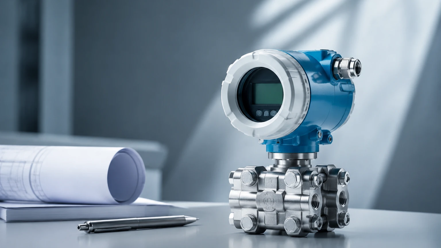
What distinguishes a differential pressure indicating transmitter from a standard DP cell is the integration of a local human-machine interface. Modern industrial transmitters usually incorporate several key components:
1. Sensing Module: High-precision diaphragms made from 316L stainless steel, Hastelloy C, or Tantalum to withstand corrosive media.
2. Digital Electronics: Microprocessor-based circuitry that converts the physical displacement of the sensor into a digital signal. This allows for linear or square-root extraction outputs.
3. Local Indicator: An integrated LCD or LED screen that displays the current pressure, level, or flow in engineering units (e.g., kPa, bar, m³, or liters).
4. Communication Protocols: Most units support 4-20mA analog signals with HART (Highway Addressable Remote Transducer), Foundation Fieldbus, or Profibus for integration into Distributed Control Systems (DCS).
Applications in Industrial Level and Flow Measurement
Differential pressure indicating transmitters are utilized across a broad spectrum of industries due to their reliability and adaptability.
Chemical and Petrochemical
In these environments, tanks are often pressurized and contain hazardous vapors. A DP transmitter allows for accurate level measurement without the need for moving parts inside the tank. By using remote seals and capillary tubes, the transmitter can be isolated from extremely hot or highly corrosive chemicals.
Water and Wastewater Treatment
DP transmitters are frequently used to monitor the head loss across filters. As a filter becomes clogged with debris, the pressure difference between the inlet and outlet increases. The indicating transmitter provides a clear visual cue to operators when a backwash cycle is required.
Oil and Gas
In the upstream and midstream sectors, these instruments monitor flow rates in pipelines and level in separators. The ability to see the pressure reading locally is invaluable during commissioning and manual bypass operations.
Selection Criteria and Technical Specifications
Choosing the correct differential pressure indicating transmitter requires a thorough analysis of the process conditions. The following table provides a general guideline for material and specification selection:
| Feature | Consideration | Recommendation |
| :— | :— | :— |
| Process Media | Corrosive or acidic fluids | Use Hastelloy C or Tantalum diaphragms |
| Pressure Range | Maximum Operating Pressure (MWP) | Ensure the sensor body can withstand the static line pressure |
| Temperature | High-temperature steam or liquids | Utilize remote seals with cooling spacers or capillaries |
| Accuracy | Required precision for billing or control | Standard units offer 0.075% accuracy; high-precision units reach 0.04% |
| Environment | Hazardous areas (Ex-zones) | Specify Intrinsically Safe (IS) or Explosion-Proof (XP) housings |
Rangeability and Turndown Ratio
Rangeability refers to the ratio between the maximum and minimum spans that the transmitter can measure while maintaining specified accuracy. A high turndown ratio (e.g., 100:1) allows a single transmitter model to be used across various applications in a plant, reducing the need for extensive spare parts inventory.
Installation and Engineering Best Practices
Proper installation is critical to ensure the longevity and accuracy of a differential pressure indicating transmitter. Incorrect piping is the most common cause of measurement errors.
Impulse Line Configuration
Impulse lines (the small-bore pipes connecting the process to the transmitter) must be installed with a specific slope to prevent gas bubbles or sediment from being trapped. For liquid applications, the transmitter should ideally be mounted below the process taps so that air bubbles can rise back into the main pipe. For gas applications, the transmitter should be mounted above the taps to allow condensate to drain away.
The Role of the Manifold
A 3-valve or 5-valve manifold is an essential accessory. It allows the transmitter to be isolated from the process for maintenance or zero-calibration without shutting down the entire line. The equalizing valve in the manifold ensures that the sensor is not damaged by over-pressure on one side during startup.
Wet Leg vs. Dry Leg
In closed-tank level applications where the vapor above the liquid might condense, a "wet leg" (a pipe filled with a stable reference liquid) is used on the low-pressure side. If the vapor does not condense, a "dry leg" is used. Modern systems often replace these with electronic remote seals to eliminate the maintenance associated with maintaining leg levels.
Limitations and Maintenance Requirements
While highly versatile, the differential pressure indicating transmitter has specific limitations that engineers must account for:
* Density Sensitivity: Since DP transmitters measure weight (hydrostatic head), any change in the liquid's density—caused by temperature fluctuations or changes in chemical concentration—will result in a level error. If density varies significantly, temperature compensation or a different technology (like radar) may be required.
* Impulse Line Clogging: In slurries or viscous fluids, impulse lines can clog. Using diaphragm seals (remote seals) can mitigate this issue by providing a flat sensing surface.
* Zero Drift: Over time, the "zero" point of the transmitter may shift due to mechanical stress or temperature cycling. Periodic zero-checks using the manifold are recommended.
Calibration Cycles
Most industrial-grade transmitters require a full calibration check every 1 to 3 years, depending on the criticality of the process and the stability of the sensor. The local indicator should be checked against the digital output to ensure the display remains accurate.
Frequently Asked Questions (FAQ)
Q: Can a differential pressure transmitter measure the level of a solid material?
No, DP transmitters are designed for liquids and gases. For solids, such as powders or grains in a silo, technologies like radar or ultrasonic level sensors are more appropriate.
Q: What is the difference between a pressure transmitter and a differential pressure transmitter?
A standard pressure transmitter measures pressure relative to a vacuum or the atmosphere (gauge pressure) using a single port. A DP transmitter measures the difference between two specific pressure points using two ports.
Q: Why is my DP transmitter reading incorrectly when the tank temperature rises?
This is likely due to a change in the density of the liquid or the fill fluid in the impulse lines/remote seals. As temperature increases, density typically decreases, leading to a lower pressure reading for the same height of liquid.
Q: Is it possible to use a DP transmitter for interface measurement?
Yes, if two immiscible liquids have different densities (e.g., oil and water), a DP transmitter can be calibrated to measure the interface level, provided the total liquid level remains above the high-pressure tap.
For further technical guidance and to find the most suitable measurement technology for your specific industrial application, please visit our Main Page for a comprehensive overview of our sensor solutions.
Download Differential Pressure Indicating Transmitter as a PDF