Hydrostatic Level Transmitter
Hydrostatic Level Transmitter
In the realm of industrial process control, the ability to accurately monitor liquid levels is fundamental to operational safety, efficiency, and inventory management. Among the diverse array of technologies available—ranging from non-contact radar to mechanical floats—the hydrostatic level transmitter stands out as a robust, reliable, and cost-effective solution. By utilizing the physical relationship between the height of a liquid and the pressure it exerts at a specific depth, these instruments provide continuous measurement in applications ranging from deep groundwater wells to complex chemical storage tanks.
This comprehensive guide serves as a practical engineering reference for selecting, installing, and maintaining hydrostatic level transmitters. As a professional manufacturer, Welk provides these insights to assist engineers in navigating the technical nuances of hydrostatic pressure measurement to ensure long-term system reliability.
Understanding the Physics: The Hydrostatic Measurement Principle
The operation of a hydrostatic level transmitter is governed by Pascal’s Law, which states that the pressure exerted by a static fluid at any point is determined by the weight of the fluid column above it. Because liquids are largely incompressible, this relationship is linear, making it an ideal basis for electronic measurement.
The Fundamental Equation
The pressure (P) at the bottom of a vessel is calculated using the following formula:
P = ρ · g · h
* P (Pressure): The hydrostatic pressure measured at the sensor diaphragm.
* ρ (Rho – Density): The mass density of the liquid (kg/m³).
* g (Gravity): The local acceleration due to gravity (standardized at approximately 9.81 m/s²).
* h (Height): The vertical distance from the sensor to the liquid surface (meters).
In a practical industrial context, if the density of the medium remains constant, the pressure measured by the transmitter is directly proportional to the level. For instance, a water column of 1 meter (3.28 feet) exerts approximately 9.81 kPa (0.1 bar or 1.42 psi) of pressure. By measuring this pressure and converting it into a standard industrial signal, such as 4-20mA or a digital protocol like RS485 Modbus, the transmitter allows for precise monitoring of the tank or reservoir contents.
The Role of Atmospheric Pressure
It is important to note that most hydrostatic measurements are "gauge pressure" measurements. In an open tank, the atmosphere exerts pressure on the surface of the liquid. To ensure the transmitter only measures the pressure of the liquid column, the back of the sensor diaphragm must be vented to the atmosphere. This "atmospheric compensation" ensures that changes in barometric pressure do not introduce errors into the level reading.
Classification of Hydrostatic Level Transmitters
Hydrostatic transmitters are engineered in various forms to accommodate different installation environments and process media. Selecting the correct design is the first step in ensuring instrument longevity.
1. Submersible Level Transmitters (Probe Style)
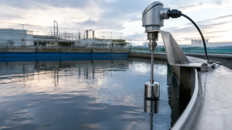
Submersible transmitters consist of a sealed sensor probe that is lowered directly into the liquid. The probe is connected to a specialized cable that contains both the electrical conductors and a small capillary vent tube.
* Applications: Deep wells, boreholes, reservoirs, wastewater lift stations, and open sumps.
* Advantages: Ease of installation (no tank penetration required at the bottom) and the ability to measure very deep levels (up to 200m or more).
2. Externally Mounted Transmitters (Side/Bottom Mount)
These units are mounted to the outside of a tank using a threaded or flanged process connection. The sensor diaphragm is in direct contact with the liquid through an opening in the tank wall.
* Applications: Industrial process tanks, chemical storage, and food and beverage processing.
* Advantages: Easier access for maintenance without removing the sensor from the medium, and suitability for tanks with high internal agitation where a suspended cable might be damaged.
3. Differential Pressure (DP) Transmitters
In closed or pressurized tanks, the headspace above the liquid may be filled with gas or steam under pressure. A standard hydrostatic sensor would measure the sum of the liquid pressure and the gas pressure, leading to an incorrect level reading. A DP transmitter uses two sensing points—one at the bottom and one at the top—to subtract the headspace pressure, leaving only the hydrostatic pressure of the liquid.
Engineering Selection Criteria: Matching Sensor to Application
When specifying a hydrostatic level transmitter, several technical parameters must be evaluated to ensure the device can withstand the process conditions while maintaining accuracy.
Material Compatibility
The "wetted parts" (the diaphragm and housing) must be chemically compatible with the liquid.
* 316L Stainless Steel: The standard for water and general industrial fluids.
* Ceramic (99% Alumina): Excellent for abrasive slurries and aggressive chemicals due to its hardness and corrosion resistance.
* Hastelloy C / Tantalum: Reserved for highly corrosive acids or specialty chemical applications.
* Cabling: For submersible units, PUR (Polyurethane) is standard for water, while FEP or PTFE is required for fuels and aggressive chemicals.
Measurement Range and Accuracy
Selecting a transmitter with the appropriate pressure range is vital. If the range is too high, the resolution and accuracy at lower levels will suffer. Conversely, exceeding the rated pressure can damage the diaphragm. Accuracy is typically expressed as a percentage of the Full Scale (FS), with standard industrial units offering ±0.5% FS and high-precision models reaching ±0.1% FS.
Selection Summary Table
| Application | Recommended Sensor Type | Diaphragm Material | Key Consideration |
| :— | :— | :— | :— |
| Potable Water Well | Submersible (Vented) | 316L Stainless Steel | Lightning protection & vent filter |
| Wastewater Sump | Submersible (Non-clog) | Ceramic or Flush 316L | Resistance to build-up and grease |
| Chemical Storage | Externally Mounted | Hastelloy or PTFE-coated | Chemical compatibility of seals |
| Fuel/Oil Tanks | Submersible or Side-mount | 316L / FEP Cable | Explosion-proof (Ex) ratings |
| Pressurized Boiler | Differential Pressure | Stainless Steel | High-temperature remote seals |
Installation Engineering and Best Practices
Even the highest-quality hydrostatic level transmitter will fail or provide inaccurate data if installed incorrectly. Following these engineering guidelines is essential for optimal performance.
1. Cable Management and Venting
For submersible sensors, the cable is a critical component. The internal vent tube must remain open to the atmosphere.
* Moisture Protection: Use a specialized junction box with a desiccant (silica gel) filter. This prevents moisture from entering the vent tube, which could lead to internal condensation and sensor drift.
* Bending Radius: Avoid sharp kinks in the cable, as this can pinch the vent tube and block atmospheric compensation.
2. Protecting Against Turbulence
In tanks with high-speed mixers or near-inlet pipes, the liquid may be turbulent. This turbulence creates dynamic pressure changes that the sensor interprets as level fluctuations.
* Stilling Wells: Install the submersible probe inside a "stilling well"—a vertical pipe with small holes that allow the liquid level to equalize while dampening waves and protecting the sensor from mechanical impact.
3. Mounting Position
For side-mounted transmitters, the sensor should be placed at a point where it will not be covered by sediment or sludge. If the tank bottom accumulates solids, mount the transmitter slightly above the bottom or use a flush-diaphragm design that prevents material from clogging the pressure port.
4. Lightning and Surge Protection
Submersible sensors used in outdoor reservoirs or deep wells are susceptible to lightning strikes and electrical surges. Selecting a transmitter with integrated surge protection and ensuring the system is properly grounded can prevent costly hardware failures during storms.

Comparative Analysis: Hydrostatic vs. Non-Contact Technologies
While hydrostatic level transmitters are highly effective, they are often compared with ultrasonic and radar technologies. Understanding the trade-offs is key to making the right engineering choice.
* Hydrostatic vs. Ultrasonic: Ultrasonic sensors are non-contact but can be affected by foam, steam, and heavy dust. Hydrostatic sensors measure the weight of the liquid, making them immune to surface conditions like foam or vapor. However, hydrostatic sensors are "wetted," meaning they must be compatible with the fluid.
* Hydrostatic vs. Radar: Radar is highly accurate and works in almost all conditions but comes at a significantly higher price point. For many standard water and oil applications, a hydrostatic transmitter provides the required accuracy at a fraction of the cost.
* The Density Factor: The primary limitation of hydrostatic measurement is its dependence on fluid density. If the density of the liquid changes (due to temperature shifts or concentration changes), the level reading will drift. In such cases, non-contact radar may be a superior choice, or the system must include density compensation.
Maintenance, Calibration, and Troubleshooting
One of the main advantages of hydrostatic technology is its low maintenance requirement. However, periodic checks are necessary to ensure continued accuracy.
Field Calibration
Most modern transmitters are factory-calibrated, but field verification is recommended annually. This can be done by comparing the transmitter output to a manual dip-tape measurement. If the transmitter supports HART protocol, the zero and span can be adjusted digitally without removing the device from the process.
Cleaning the Diaphragm
In wastewater or slurry applications, the diaphragm may become coated with debris. Cleaning should be done with a soft cloth and a compatible solvent. Never use a sharp object (like a screwdriver) to clean the diaphragm, as the metal is extremely thin and easily punctured.
Common Troubleshooting Steps
* Erratic Readings: Check for moisture in the vent tube or electrical interference on the signal line. Ensure the cable shield is grounded at only one end.
* Constant Output (e.g., 4mA or 20mA): This often indicates a broken wire, a collapsed vent tube, or a sensor that has been over-pressured beyond its limit.
* Slow Response: This may indicate that the pressure port is partially clogged with sediment or viscous fluid.
Summary and Next Steps
The hydrostatic level transmitter remains a cornerstone of industrial instrumentation due to its simplicity, reliability, and adaptability. Whether you are monitoring a remote groundwater well or a high-pressure process vessel, understanding the physics of pressure and the requirements of your specific media will lead to a successful installation.
As you evaluate your project requirements, it is essential to partner with a manufacturer that provides both high-quality hardware and technical expertise. For a detailed look at product specifications, application notes, and custom OEM/ODM services, we invite you to visit our Main Page to review product options and application support.
Frequently Asked Questions (FAQs)
Q: How does temperature affect hydrostatic level measurement?
A: Temperature affects the density of the liquid. As a liquid heats up, it typically expands and becomes less dense. Since the transmitter measures pressure, a decrease in density will result in a lower pressure reading even if the actual volume remains the same. For high-precision applications with fluctuating temperatures, density compensation is required.
Q: Can I cut the cable of a submersible level transmitter?
A: While it is physically possible to cut the cable, it is not recommended without specialized tools. The cable contains a vent tube that must be kept open and protected. If you must shorten the cable, ensure the vent tube is properly terminated in a vented junction box.
Q: Is hydrostatic measurement suitable for tanks with agitators?
A: Yes, but with precautions. Side-mounted transmitters are generally preferred. If using a submersible probe, it must be installed in a stilling well to prevent the moving liquid from pulling on the cable or causing "noise" in the pressure reading.
Q: What is the difference between a gauge and absolute pressure transmitter for level?
A: A gauge pressure transmitter is vented to the atmosphere and is used for open tanks. An absolute pressure transmitter is sealed and measures pressure relative to a vacuum; these are rarely used for level measurement unless the headspace pressure is also being measured by a second absolute sensor to calculate the difference.
Q: Can hydrostatic sensors be used in hazardous areas?
A: Yes. Welk offers hydrostatic level transmitters with Intrinsic Safety (Ex ia) and Flameproof (Ex d) certifications for use in environments containing explosive gases or dusts, such as oil refineries and chemical plants.