Dp Gauge
Dp Gauge
In the realm of industrial process control, the differential pressure gauge, commonly referred to as a dp gauge, serves as a fundamental instrument for monitoring pressure drops, flow rates, and liquid levels. Unlike a standard pressure gauge that measures pressure relative to the atmosphere (gauge pressure) or a vacuum (absolute pressure), a dp gauge specifically measures the difference between two distinct pressure points in a system. This capability is critical for applications where the relative pressure between two zones determines the efficiency, safety, or status of a process.
For engineers and plant operators, understanding the mechanics, selection criteria, and installation nuances of a dp gauge is essential for maintaining system integrity. This guide provides a comprehensive technical overview of differential pressure measurement, focusing on its application in level sensing and process monitoring.
Measurement Principles of the DP Gauge
The operating principle of a dp gauge is based on the mechanical or electronic sensing of two opposing pressures. The instrument features two inlet ports: a high-pressure (HP) port and a low-pressure (LP) port. The internal sensing element—typically a diaphragm, bellows, or capsule—is positioned between these two ports.
Mechanical Deflection
When the pressure at the HP port exceeds the pressure at the LP port, the sensing element deflects toward the low-pressure side. In a mechanical dp gauge, this physical displacement is transmitted through a geared movement or a magnetic coupling to a pointer on a dial. The amount of deflection is proportional to the pressure difference ($ΔP$), allowing for a direct readout of the differential value.
Hydrostatic Level Measurement
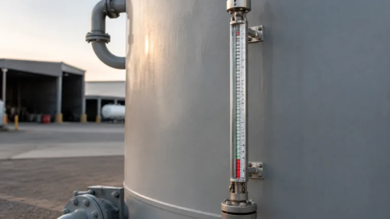
In level measurement applications, a dp gauge utilizes the principle of hydrostatic head pressure. For an open tank, the high-pressure side is connected to the bottom of the vessel, while the low-pressure side is vented to the atmosphere. The pressure exerted by the liquid column is calculated using the formula:
$$P = ρ · g · h$$
Where:
* P is the hydrostatic pressure.
* ρ (rho) is the density of the liquid (kg/m³).
* g is the acceleration due to gravity (approximately 9.81 m/s²).
* h is the height of the liquid (m).
For pressurized vessels, the LP port of the dp gauge is connected to the top of the tank to cancel out the effect of the internal gas pressure, ensuring that only the pressure generated by the liquid height is measured.
Key Applications in Industrial Environments
While the dp gauge is a versatile tool, its primary utility in B2B industrial sectors like water treatment, chemical processing, and oil and gas revolves around three core functions:
1. Filter Monitoring: One of the most common uses for a dp gauge is to monitor the cleanliness of filter elements. By measuring the pressure drop across a filter, operators can determine when the element is clogged and requires cleaning or replacement. A rising differential pressure indicates increased resistance due to contaminant buildup.
2. Level Measurement in Closed Tanks: In industries handling liquefied gases or volatile chemicals, tanks are often pressurized. A standard level sensor would be influenced by the vapor space pressure. A dp gauge compensates for this by referencing the vapor pressure on the LP side, providing an accurate liquid level reading regardless of tank pressure fluctuations.
3. Flow Rate Indication: When paired with a primary flow element such as an orifice plate, Venturi tube, or flow nozzle, a dp gauge can calculate flow rates. The pressure drop created by the restriction in the pipe is proportional to the square of the flow velocity (Bernoulli's principle).
Practical Selection Table for DP Gauges
Selecting the right dp gauge requires a balance between accuracy requirements, environmental conditions, and budget. The following table compares common types of differential pressure instruments used in industrial automation.
| Feature | Mechanical Piston/Diaphragm Gauge | Digital DP Gauge / Transmitter | Bellows-Actuated DP Gauge |
| :— | :— | :— | :— |
| Primary Use | Local indication, filter status | Control loops, remote monitoring | Low-pressure gas applications |
| Accuracy | ±2% to ±5% of Full Scale | ±0.075% to ±0.25% of URL | ±1% to ±2% of Full Scale |
| Power Required | None (Mechanical) | 24V DC (4-20mA / HART) | None (Mechanical) |
| Overpressure Limit | Moderate | High (Internal protection) | Low to Moderate |
| Cost | Cost-effective | Higher investment | Mid-range |
| Signal Output | None (Optional switches) | Analog, Digital, Wireless | None (Optional switches) |
For organizations looking to integrate these instruments into a broader automation strategy, reviewing the latest specifications on the Main Page of reputable manufacturers is a recommended first step.
Key Evaluation Criteria for Industrial DP Gauges
When specifying a dp gauge for a project, engineers must look beyond the basic pressure range. Several technical factors influence the longevity and reliability of the instrument:
Static Pressure Rating (Working Pressure)
It is vital to distinguish between the differential pressure range (e.g., 0-500 mbar) and the maximum static pressure the gauge can withstand (e.g., 100 bar). In a high-pressure pipeline, the differential might be small, but the gauge body must be rated for the full system pressure to prevent catastrophic failure.
Wetted Materials
The materials in contact with the process fluid must be chemically compatible. While Stainless Steel 316L is standard, aggressive chemical applications may require Monel, Hastelloy, or PTFE-coated diaphragms. For water treatment, standard corrosion-resistant alloys are typically sufficient.
Environmental and Safety Ratings
In oil and gas or chemical sectors, the dp gauge may need to operate in hazardous areas. Look for ATEX or IECEx certifications for electronic versions. For outdoor installations, an IP65 or IP67 ingress protection rating is necessary to prevent moisture and dust from damaging the internal movement or electronics.
Square Root Extraction
If the dp gauge is being used for flow measurement, the relationship between pressure and flow is non-linear (square root). Digital transmitters can perform square root extraction internally to provide a linear flow signal, whereas mechanical gauges may require a specialized "square root" dial scale.
Installation Considerations and Best Practices
The accuracy of a dp gauge is often more dependent on the installation than the instrument itself. Improper mounting or piping can lead to significant measurement errors.
1. Impulse Piping: The lines connecting the process to the gauge (impulse lines) should be as short as possible to minimize lag and temperature effects. For liquid service, the gauge should ideally be mounted below the process taps to allow gas bubbles to vent back into the tank or pipe. For gas service, the gauge should be mounted above the taps to allow condensate to drain away.
2. Manifold Valves: A 3-way or 5-way valve manifold should always be installed with a dp gauge. These manifolds allow the operator to isolate the gauge from the process, equalize the pressure between the HP and LP sides for zero-point calibration, and bleed off trapped air or liquid without shutting down the entire system.
3. Wet Leg vs. Dry Leg: In level measurement for pressurized tanks, if the vapor on the LP side can condense at ambient temperatures, a "wet leg" (a pipe filled with a constant head of liquid) is used to provide a stable reference. If the vapor does not condense, a "dry leg" is used. The dp gauge must be calibrated to account for the constant head pressure of a wet leg.
4. Mounting Position: Mechanical gauges are sensitive to gravity. If a gauge is calibrated for vertical mounting but installed horizontally, the weight of the internal mechanism may cause a zero-shift error.
Limitations and Common Risks
Despite their reliability, dp gauge installations face several common challenges:
* Overpressure Events: If one side of the gauge is suddenly vented while the other remains under high pressure, the sensing diaphragm can be permanently deformed. High-quality industrial gauges include overpressure protection mechanisms to prevent this.
* Temperature Fluctuations: Extreme heat or cold can change the density of the fluid in the impulse lines or affect the elasticity of the sensing element. In outdoor environments, heat tracing or insulation may be required for impulse lines to prevent freezing or boiling.
* Clogging and Sedimentation: In wastewater or slurry applications, the small-diameter impulse lines can become blocked by solids. Using diaphragm seals (chemical seals) can isolate the gauge from the messy process fluid, transmitting pressure via a capillary filled with silicone oil.
Frequently Asked Questions (FAQs)
Q: How often should a dp gauge be calibrated?
A: For most industrial applications, an annual calibration check is recommended. However, in critical safety loops or high-precision chemical processes, six-month intervals may be required. Always check for "zero shift" whenever the system is depressurized.
Q: Can a dp gauge measure the level of a vacuum tank?
A: Yes. Because the dp gauge measures the relative difference between the bottom and top of the tank, it remains accurate regardless of whether the internal tank pressure is positive or negative (vacuum), provided the gauge body is rated for vacuum service.
Q: What is the difference between a DP gauge and a DP transmitter?
A: A dp gauge provides a local visual readout on a dial and requires no power. A DP transmitter converts the pressure difference into an electrical signal (like 4-20mA) for transmission to a PLC or SCADA system. Many modern facilities use a combination of both for local and remote monitoring.
Q: Why is my dp gauge reading incorrectly after a period of stable operation?
A: The most common causes are leaks in the impulse piping, trapped air in a liquid-filled line, or a partially closed manifold valve. Inspect all connections for signs of leakage and ensure the equalization valve on the manifold is fully closed during operation.
Conclusion
The dp gauge remains a cornerstone of industrial instrumentation due to its mechanical simplicity and its ability to solve complex measurement challenges in pressurized environments. By carefully considering the static pressure, material compatibility, and installation geometry, engineers can ensure long-term accuracy and safety in their level and flow monitoring systems. For those seeking specific product specifications or customized measurement solutions, visiting the Main Page of an established manufacturer provides the technical data necessary to make an informed procurement decision. Whether for a simple filter check or a complex pressurized tank level system, the right differential pressure instrument is key to process optimization.