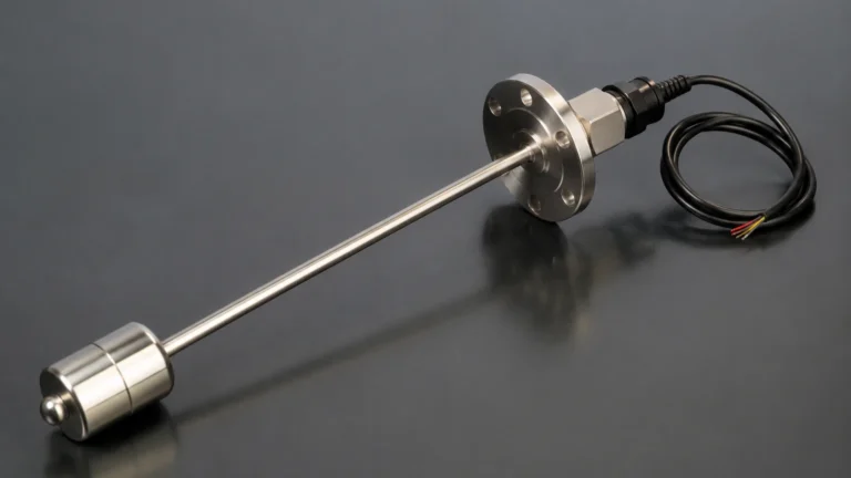
Dp Transducer
Dp Transducer
In the landscape of industrial process control, the differential pressure (DP) transducer remains one of the most versatile and widely implemented instruments for level measurement. By calculating the pressure difference between two points, a dp transducer provides critical data for monitoring liquid levels in both vented and pressurized vessels. This article explores the fundamental principles, selection criteria, and technical considerations for integrating DP technology into industrial workflows.
Measurement Principles of DP Transducers
The operation of a dp transducer for level measurement is based on the principle of hydrostatic head pressure. In any column of liquid, the pressure exerted at the base is directly proportional to the height of the liquid and its specific gravity. The fundamental formula used is:
P = ρ × g × h
Where:
* P is the hydrostatic pressure.
* ρ (Rho) is the density of the liquid.
* g is the acceleration due to gravity (approximately 9.81 m/s²).
* h is the height of the liquid column.
In a level measurement application, the dp transducer measures the difference between the high-pressure (HP) side and the low-pressure (LP) side.
Open (Vented) Tanks
In an open tank, the surface of the liquid is exposed to atmospheric pressure. The LP side of the transducer is vented to the atmosphere, while the HP side is connected to the bottom of the tank. The transducer measures the hydrostatic pressure of the liquid column minus the atmospheric pressure. Since the LP side also experiences atmospheric pressure, the two cancel each other out, leaving a net pressure proportional to the liquid level.
Closed (Pressurized) Tanks
In pressurized vessels, such as those found in chemical processing or oil and gas applications, the space above the liquid is filled with gas or vapor at a pressure higher than atmospheric. To accurately measure the level, the LP side of the dp transducer must be connected to the top of the tank. This ensures that the static pressure (the pressure of the gas) is subtracted from the total pressure at the bottom, isolating the hydrostatic pressure generated by the liquid itself.
For more information on various measurement technologies, you can visit the Main Page.
Key Components and Construction
A professional-grade dp transducer consists of several critical components designed to withstand harsh industrial environments:
1. Sensing Element (Diaphragm): Usually made of stainless steel, Hastelloy, or Monel, the diaphragm flexes in response to pressure changes. This mechanical movement is converted into an electrical signal.
2. Fill Fluid: Silicone oil or specialized inert fluids transfer the pressure from the isolation diaphragm to the internal sensor.
3. Electronics Housing: Contains the signal processing circuitry, which converts the raw sensor data into a standard industrial output, such as 4-20mA, HART, or Modbus.
4. Process Connections: These include threaded ports, flanges, or remote seals depending on the media being measured.
Practical Selection Table
Choosing the right dp transducer requires an understanding of the process conditions. The following table provides a general guide for selection based on common industrial scenarios.
| Application Requirement | Recommended DP Configuration | Reason |
| :— | :— | :— |
| Clean, non-corrosive liquids | Standard impulse piping | Cost-effective and reliable for water or light oils. |
| Viscous or slurry-like media | Remote Diaphragm Seals | Prevents clogging of impulse lines and protects the sensor. |
| High-temperature fluids | Capillary-mounted seals | Isolates the transducer electronics from extreme process heat. |
| Highly corrosive chemicals | Tantalum or PTFE-coated diaphragms | Ensures long-term durability against chemical attack. |
| Sanitary/Food & Beverage | Tri-clamp or hygienic flanges | Eliminates dead spaces where bacteria could grow. |
| Vacuum applications | Specialized vacuum-rated fill fluids | Prevents outgassing of fill fluids under low-pressure conditions. |
Installation Considerations
The accuracy of a dp transducer is heavily dependent on proper installation. Engineers must account for several factors to ensure the integrity of the measurement signal.
Impulse Piping
Impulse lines are the small-bore pipes that connect the process to the transducer. To avoid errors, these lines should be as short as possible. For gas applications, the lines should slope upward toward the process to allow condensate to drain back into the tank. For liquid applications, the lines should slope downward to allow air bubbles to escape back into the vessel.
Zero Elevation and Suppression
In many installations, the dp transducer is not mounted exactly at the same level as the zero-point of the tank.
* Zero Suppression: Used when the transducer is mounted below the tank bottom. The weight of the liquid in the impulse line creates a positive pressure even when the tank is empty. The electronics must be calibrated to "suppress" this initial pressure.
* Zero Elevation: Used in closed-tank systems with a "wet leg" (where the LP impulse line is filled with liquid to prevent vapor condensation). This creates a higher pressure on the LP side than the HP side when the tank is empty, requiring a "zero elevation" calibration.
Remote Seals and Capillaries
When measuring hazardous or extremely hot media, remote seals are used. These consist of a diaphragm at the process point connected to the transducer via a capillary tube filled with oil. While effective, capillaries are sensitive to temperature fluctuations; as the ambient temperature changes, the fill fluid expands or contracts, which can introduce small measurement errors if not properly compensated.

Limitations and Challenges
While the dp transducer is a robust tool, it is not without limitations:
* Density Sensitivity: Since DP technology measures mass (via pressure), any change in liquid density (due to temperature or concentration changes) will result in a level error. If the density decreases, the pressure at the bottom decreases, and the transducer will report a lower level even if the physical height remains the same.
* Maintenance of Impulse Lines: In many industries, impulse lines are prone to freezing, clogging, or leaking. This often requires the installation of heat tracing or regular purging, increasing the total cost of ownership.
* Static Pressure Limits: Every dp transducer has a maximum static pressure rating. Exceeding this limit can damage the internal sensing element, even if the differential pressure remains within the calibrated range.
Comparison with Alternative Technologies
In modern industrial automation, DP transducers are often compared with non-contact methods like radar or ultrasonic sensors.
* Vs. Radar: Radar is unaffected by density changes and does not require process penetrations at the bottom of the tank. However, radar can be significantly more expensive and may struggle with heavy foam or complex internal tank structures where a dp transducer would perform reliably.
* Vs. Ultrasonic: Ultrasonic sensors are cost-effective for simple water applications but are sensitive to temperature gradients and vapors in the headspace. A dp transducer is generally more reliable in pressurized chemical reactors where vapors are prevalent.
Frequently Asked Questions (FAQ)
Q: How often should a dp transducer be calibrated?
A: Calibration frequency depends on the criticality of the process and the stability of the instrument. Most industrial standards recommend a full calibration check every 12 to 24 months, though many modern digital transducers offer diagnostic features that can extend these intervals.
Q: Can a dp transducer measure the interface between two liquids?
A: Yes. By knowing the densities of both the heavy and light liquids, a dp transducer can be calibrated to detect the interface level in a separator or settling tank.
Q: What is the impact of ambient temperature on DP measurements?
A: Ambient temperature can affect the electronics and the fill fluid in capillaries. High-quality transducers include internal temperature compensation to minimize these effects, but shielding the instrument from direct sunlight or extreme cold is always recommended.
Q: What units are typically used for DP level measurement?
A: In the metric system, pressure is usually measured in kilopascals (kPa), millibar (mbar), or meters of water column (mH2O). In imperial systems, inches of water column (inH2O) or PSI are common.
Conclusion and Next Steps
The dp transducer remains a fundamental component in the toolkit of process engineers. Its ability to provide reliable level data in high-pressure, high-temperature, and corrosive environments makes it indispensable across the water treatment, chemical, and oil and gas sectors. When selecting a device, it is essential to confirm the fluid density, vessel pressure, and potential for clogging to ensure the chosen instrument meets the long-term demands of the application.
For technical support and to explore a wide range of industrial level measurement solutions, including radar, ultrasonic, and hydrostatic options, please refer to the Main Page for detailed product specifications and application guidance.