E+h Flow Meter
E+h Flow Meter
In the landscape of industrial process automation, flow measurement represents one of the most critical parameters for ensuring operational efficiency, safety, and fiscal accountability. The e+h flow meter portfolio, produced by Endress+Hauser, is recognized globally for its diverse range of measurement technologies tailored to specific fluid properties and environmental conditions. Selecting the appropriate flow meter requires a deep understanding of the underlying physical principles, the characteristics of the medium being measured, and the specific requirements of the piping system.
This guide examines the primary measurement technologies used in e+h flow meters, provides practical selection criteria, and outlines essential installation and maintenance considerations for engineering professionals.
Measurement Principles of Flow Instrumentation
Before selecting a specific e+h flow meter, it is essential to understand the physical principles that govern different measurement technologies. Each method has unique advantages depending on whether the fluid is a liquid, gas, or steam, and whether it is conductive or non-conductive.
Electromagnetic Flow Measurement
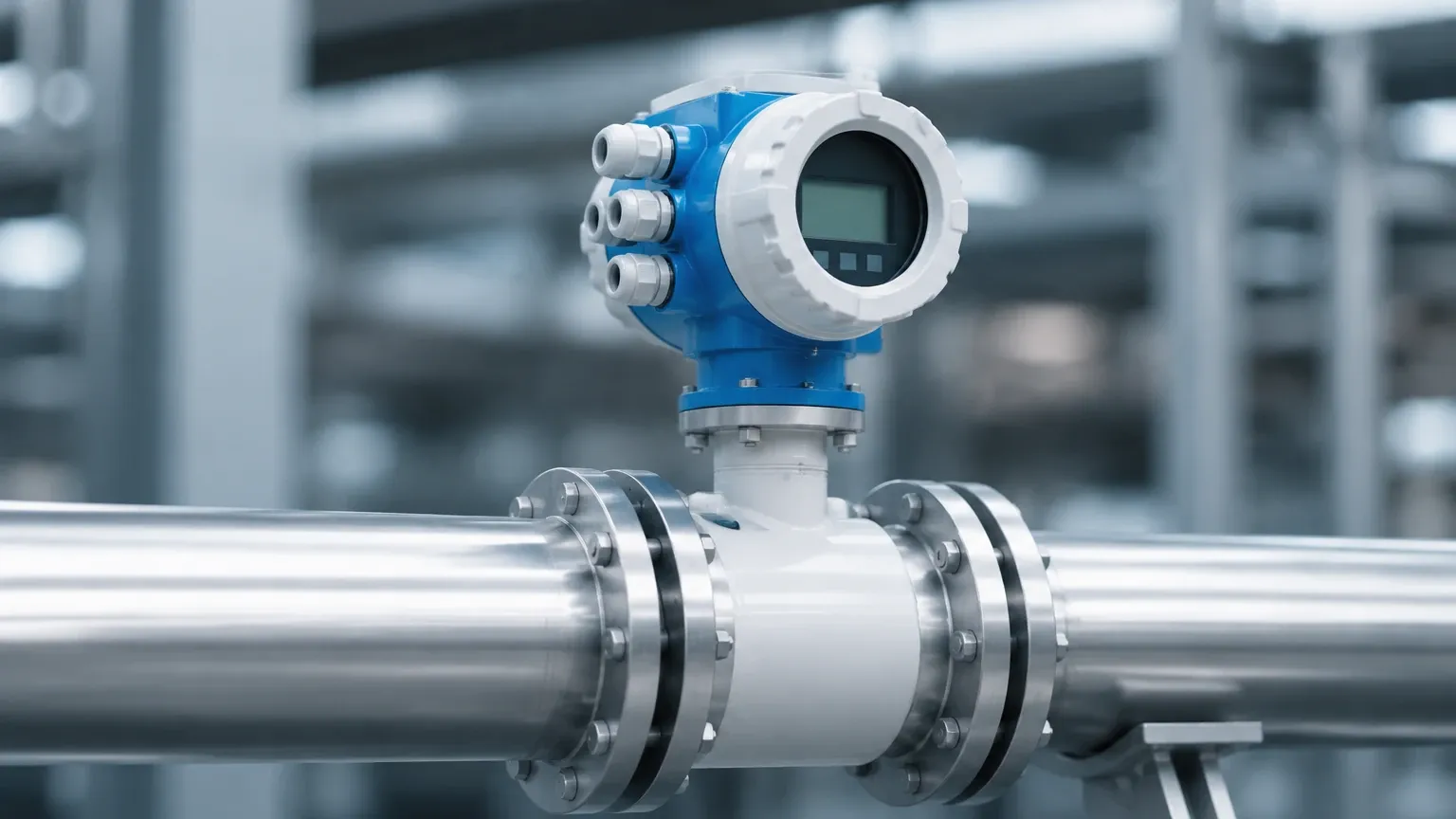
Electromagnetic flow meters, such as the Proline Promag series, operate based on Faraday’s Law of Induction. This law states that a conductor moving through a magnetic field induces an electrical voltage. In this application, the conductive liquid acts as the conductor. Two field coils inside the meter generate a constant magnetic field. As the fluid flows through the pipe, it generates a voltage proportional to the flow velocity. This voltage is picked up by electrodes and converted into a volumetric flow rate.
Coriolis Mass Flow Measurement
Coriolis meters, exemplified by the Proline Promass series, measure mass flow directly rather than volume. The principle is based on the Coriolis effect: when a fluid moves through a vibrating tube, it exerts a force on the tube, causing it to twist. The degree of twist is directly proportional to the mass flow rate. Additionally, the resonant frequency of the tube vibration allows for the simultaneous measurement of fluid density.
Ultrasonic Flow Measurement
Ultrasonic meters, such as the Proline Prosonic series, typically use the transit-time differential method. Two sensors are mounted on the pipe, each functioning as a transmitter and a receiver. They alternate sending ultrasonic pulses through the fluid. Pulses traveling with the flow move faster than those traveling against it. The time difference between the two signals is used to calculate the flow velocity.
Vortex Flow Measurement
Vortex meters, like the Proline Prowirl, utilize the Karman vortex street principle. When a fluid flows past a bluff body (a non-streamlined object) placed in the pipe, vortices are shed alternately on each side. The frequency of this vortex shedding is directly proportional to the flow velocity over a wide range of Reynolds numbers.
Thermal Mass Flow Measurement
Thermal meters, such as the Proline t-mass, measure the mass flow of gases based on the principle of heat transfer. A heated sensor is placed in the flow stream, and the cooling effect of the gas moving past the sensor is measured. The amount of heat lost is proportional to the mass flow of the gas, independent of pressure and temperature changes.
Practical Selection Criteria
Choosing the right e+h flow meter involves evaluating the process conditions against the capabilities of each technology. The following table provides a general comparison of common flow measurement technologies.
Flow Technology Comparison Table
| Technology | Suitable Media | Typical Accuracy | Pressure Loss | Requirements |
| :— | :— | :— | :— | :— |
| Electromagnetic | Conductive Liquids | ±0.2% to ±0.5% | Negligible | Minimum conductivity > 5 μS/cm |
| Coriolis | Liquids, Gases | ±0.1% | Moderate | Requires stable mounting |
| Ultrasonic | Clean Liquids, Gases | ±0.5% to ±1.0% | None | Requires specific pipe profiles |
| Vortex | Steam, Gas, Liquids | ±0.75% to ±1.0% | Moderate | High Reynolds number required |
| Thermal | Gases | ±1.0% to ±1.5% | Low | Clean, dry gas preferred |
Key Evaluation Factors
1. Fluid Conductivity: For electromagnetic meters, the fluid must have a minimum conductivity. For non-conductive fluids like hydrocarbons or demineralized water, Coriolis or ultrasonic technologies are preferred.
2. Accuracy Requirements: If the application involves custody transfer or high-value chemical dosing, the high precision of a Coriolis meter (±0.1%) is often necessary.
3. Process Temperature and Pressure: Vortex meters are highly robust and suitable for high-temperature steam applications, whereas some ultrasonic sensors may have lower temperature limits.
4. Installation Footprint: Clamp-on ultrasonic meters require no pipe cutting, making them ideal for retrofitting, while Coriolis meters may require significant space and support due to their weight.
For projects involving comprehensive fluid management, it is often necessary to integrate flow data with level measurement. You can Review product options and application support to see how different instrumentation types complement each other in industrial automation.
Installation and Commissioning Considerations
The performance of an e+h flow meter is heavily dependent on correct installation. Even the most accurate meter will provide unreliable data if installed improperly.
Inlet and Outlet Runs
Most flow meters (especially Vortex and Ultrasonic) require a specific length of straight pipe upstream (inlet) and downstream (outlet) to ensure a stable flow profile. Turbulent flow caused by elbows, valves, or pumps can introduce significant errors. Typically, an inlet run of 10 to 20 pipe diameters (DN) and an outlet run of 5 DN are recommended, though some modern "0 x DN" electromagnetic meters have reduced these requirements.
Pipe Orientation and Filling
For liquid applications, the pipe must always be completely full. Air bubbles or partially filled pipes will cause measurement errors or signal loss.
- Vertical Upward Flow: This is the ideal orientation for liquid flow, as it ensures the pipe remains full and prevents sediment buildup.
- Horizontal Flow: The meter should be placed in a low section of the piping (a U-section) to ensure it stays flooded.
- Electromagnetic Specifics: In horizontal pipes, electrodes should be positioned horizontally (3 o’clock and 9 o’clock positions) to prevent interference from air bubbles at the top or sediment at the bottom.
Grounding and Shielding
Electromagnetic flow meters are sensitive to electrical noise. Proper grounding is essential for a stable signal. This often involves using grounding rings if the pipe is made of non-conductive material (like plastic or lined steel) to ensure the fluid is at the same electrical potential as the meter.
Operational Limitations and Common Risks
While e+h flow meters are engineered for reliability, certain conditions can compromise their performance:
* Gas Entrainment: In liquid flow, the presence of gas bubbles can severely affect Coriolis and Ultrasonic meters. While some advanced Coriolis meters feature "multi-phase" compensation, excessive gas can still lead to signal "slugging."
* Scaling and Coating: In wastewater or chemical applications, the buildup of material on the inner walls of the meter or on the electrodes (in electromagnetic meters) can cause drift. Regular inspection or the use of self-cleaning electrodes may be required.
* Vibration: Coriolis meters are sensitive to external mechanical vibrations. If the meter is installed near a heavy pump or vibrating machinery without proper damping, the measurement accuracy will degrade.
* Cavitation: If the pressure drops too low at the meter location, the liquid may vaporize (cavitation), damaging the internal components and causing erratic readings.
Integrating Flow and Level Measurement
In many B2B industrial applications, such as tank farm management or chemical processing, flow and level measurements are used together to provide a complete picture of inventory and process efficiency. For example, a flow meter measures the rate of fluid entering a vessel, while a radar or ultrasonic level sensor monitors the actual volume stored. Discrepancies between these two values can indicate leaks, evaporation, or measurement drift.
Welk provides specialized solutions in the level measurement domain, including radar level meters and hydrostatic transmitters, which are frequently used alongside e+h flow meter installations to ensure comprehensive process control. Understanding the synergy between these technologies is vital for plant engineers designing automated systems.
Frequently Asked Questions (FAQ)
Q: Can an electromagnetic flow meter measure oil or fuel?
A: No. Most oils and fuels are non-conductive. Electromagnetic meters require a minimum conductivity (usually > 5 μS/cm). For these fluids, a Coriolis, Ultrasonic, or Positive Displacement meter should be used.
Q: What is the difference between mass flow and volumetric flow?
A: Volumetric flow measures the space the fluid occupies (e.g., liters per minute), which can change with temperature and pressure. Mass flow measures the actual amount of matter (e.g., kilograms per minute), which remains constant regardless of environmental changes. Coriolis and thermal meters measure mass flow.
Q: How often should an e+h flow meter be calibrated?
A: Calibration frequency depends on the criticality of the application and regulatory requirements. Many industrial users perform a verification check annually. Modern e+h meters often include Heartbeat Technology, which allows for internal verification without interrupting the process.
Q: Can I install a flow meter immediately after a pump?
A: It is not recommended. Pumps create significant turbulence and pressure pulsations. A minimum straight run or a flow conditioner should be placed between the pump and the meter to ensure accurate measurement.
Q: Are ultrasonic flow meters as accurate as electromagnetic ones?
A: In many clean-water applications, they are comparable (±0.5%). However, electromagnetic meters are generally more robust for slurries or fluids with solids, while ultrasonic meters offer the advantage of being non-intrusive (clamp-on).
For further technical specifications and to explore how level measurement instruments can be integrated into your flow control systems, visit the Main Page for detailed product information and engineering support.