Electromagnetic Flow Meter Principle
Electromagnetic Flow Meter Principle
In the landscape of industrial process control, the ability to accurately measure the flow rate of conductive liquids is fundamental to operational efficiency, safety, and billing accuracy. Among the various technologies available, the electromagnetic flow meter—often referred to as a magmeter—stands out for its lack of moving parts and its ability to provide high-precision measurements across a wide range of pipe sizes. Understanding the electromagnetic flow meter principle is essential for engineers and plant managers who must select, install, and maintain these critical instruments in sectors such as water treatment, chemical processing, and industrial automation.
The Core Physics: Faraday’s Law of Induction
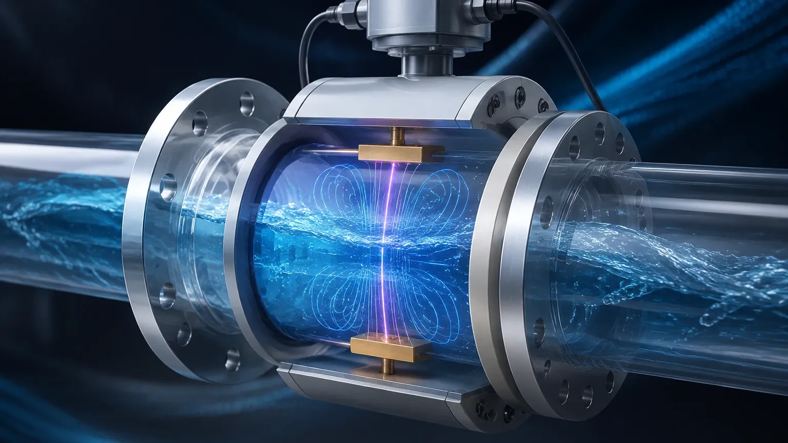
The fundamental electromagnetic flow meter principle is based on Faraday’s Law of Electromagnetic Induction, a discovery made by Michael Faraday in 1831. The law states that a voltage is induced when a conductor moves through a magnetic field. In the context of a flow meter, the "conductor" is the liquid itself. For this principle to function, the liquid must be electrically conductive.
The mathematical representation of this principle is expressed as:
E = B × v × D × k
Where:
* E is the induced voltage (signal) generated in the liquid.
* B is the strength of the magnetic field created by the meter’s coils.
* v is the average velocity of the liquid flowing through the pipe.
* D is the internal diameter of the pipe (the distance between the electrodes).
* k is a constant or calibration factor specific to the meter design.
When the conductive fluid flows through a magnetic field generated by coils located on the outside of the flow tube, it acts as a moving conductor. This movement induces a voltage that is perpendicular to both the flow direction and the magnetic field. This voltage is captured by two electrodes mounted on the inner walls of the pipe. Because the magnetic field strength (B) and the pipe diameter (D) are fixed values, the induced voltage (E) is directly proportional to the velocity (v) of the fluid. By calculating the velocity and knowing the cross-sectional area of the pipe, the transmitter can determine the volumetric flow rate.
Key Components of an Electromagnetic Flow System
An electromagnetic flow meter consists of two primary parts: the sensor (the part installed in the pipeline) and the transmitter (the electronic unit that processes the signal). To understand how the electromagnetic flow meter principle is applied in a B2B industrial environment, one must look at the internal architecture of these components.
1. The Flow Tube and Lining
The flow tube is typically constructed from non-magnetic stainless steel. Because the tube itself would short-circuit the induced voltage if it were conductive, the interior is lined with an insulating material. This lining ensures that the voltage generated in the fluid is directed to the electrodes rather than the pipe wall. Common lining materials include PTFE (Teflon), Neoprene, and Hard Rubber, chosen based on the chemical compatibility and temperature of the process fluid.
2. Magnetic Coils
Coils are placed either inside or outside the flow tube to generate a stable magnetic field. In modern industrial magmeters, these coils are usually excited by a pulsed DC (direct current) signal. This pulsed DC excitation is preferred over AC excitation because it helps eliminate noise and provides a more stable zero point, which is critical for long-term accuracy.
3. Electrodes
A pair of electrodes is positioned opposite each other, flush with the lining. These electrodes "pick up" the induced voltage. Since they are in direct contact with the process fluid, they must be made of materials that resist corrosion and abrasion. For a broader look at how these sensors integrate into wider plant systems, engineers often visit the Main Page to review product options and application support provided by manufacturers like Welk.
Technical Selection and Material Compatibility
Selecting the right electromagnetic flow meter requires a deep understanding of the process media. Since the electromagnetic flow meter principle relies on the fluid's conductivity, the first requirement is that the fluid must meet a minimum conductivity threshold, typically 5 μS/cm (microsiemens per centimeter). This makes magmeters unsuitable for hydrocarbons, distilled water, or gases.
Material Selection Guide
| Component | Material Options | Typical Applications |
| :— | :— | :— |
| Lining | PTFE / PFA | Highly corrosive chemicals, high temperatures |
| | Neoprene / Hard Rubber | Water treatment, general purpose |
| | Polyurethane | Abrasive slurries, wastewater |
| Electrodes | Stainless Steel 316L | Clean water, mildly corrosive liquids |
| | Hastelloy C | Aggressive chemicals, acids |
| | Tantalum / Platinum | Highly concentrated acids, extreme environments |
| | Tungsten Carbide | Slurries with high solid content |
Installation Best Practices for Accuracy
To ensure the electromagnetic flow meter principle is leveraged effectively, the physical installation must adhere to specific engineering standards. Failure to follow these guidelines can result in signal noise, instability, or significant measurement errors.
1. The Full Pipe Requirement
The most critical installation rule is that the pipe must be completely full of liquid. If there is air or gas trapped in the pipe, the meter will read the velocity of the liquid but assume the entire cross-section is full, leading to an overestimation of the flow rate. Installing the meter in a vertical pipe with upward flow is the most reliable way to ensure a full pipe.
2. Straight Pipe Runs
Flow profiles must be stable for the meter to calculate an accurate average velocity. Turbulence caused by valves, pumps, or elbows can distort the flow profile. Generally, a straight run of 5 diameters (5D) upstream and 2 to 3 diameters (3D) downstream of the meter is required. If space is limited, high-performance meters with specialized coil configurations may reduce these requirements.
3. Grounding
Because the induced voltage signal is very small (often in the millivolt range), it is susceptible to electrical noise. Proper grounding is essential to ensure the fluid and the meter are at the same electrical potential. This is usually achieved using grounding rings or a third grounding electrode if the pipeline is made of non-conductive material like PVC or is lined.
Limitations and Operational Constraints
While the electromagnetic flow meter principle offers numerous advantages, such as zero pressure drop and high turndown ratios, it is not a universal solution. Engineers must be aware of the following constraints:
* Conductivity Limits: As mentioned, non-conductive fluids like oils, alcohols, and demineralized water cannot be measured.
* Vacuum Conditions: Certain lining materials, particularly PTFE, can collapse or peel away from the tube wall under vacuum conditions if not properly designed with mechanical anchors.
* Temperature and Pressure: The maximum operating temperature is limited by the lining and potting materials, typically capping around 150°C to 180°C for high-end PFA linings.
* Coating and Scaling: If the fluid tends to leave deposits (such as calcium scaling or oily films) on the electrodes, the signal may be insulated or shorted, requiring periodic cleaning or the use of ultrasonic electrode cleaning features.
Comparison with Alternative Technologies
In industrial applications, magmeters are often compared with ultrasonic or vortex flow meters. Unlike vortex meters, magmeters have no minimum Reynolds number requirement, meaning they perform well at very low flow velocities (as low as 0.1 m/s). Compared to ultrasonic meters, magmeters are generally more robust in applications involving slurries or liquids with entrained solids, provided the solids do not exceed the concentration limits that might interfere with the magnetic field.
For organizations managing complex fluid systems, integrating these flow measurements with level instrumentation provides a holistic view of process dynamics. Reliable manufacturers like Welk provide a suite of tools, including radar and ultrasonic level sensors, to complement flow data. You can explore these integrated solutions on the Main Page.
Frequently Asked Questions
Q: Can electromagnetic flow meters measure the flow of steam or air?
No. The electromagnetic flow meter principle requires a conductive liquid. Gases and vapors do not have the necessary electrical conductivity to induce a measurable voltage.
Q: How does fluid viscosity affect the accuracy?
One of the primary benefits of magmeters is that they are generally independent of viscosity, density, and temperature, provided the fluid remains conductive and the flow profile is developed.
Q: What is the typical lifespan of a magmeter?
Because there are no moving parts to wear out, a well-specified magmeter can last 10 to 20 years. The primary failure points are usually lining wear in abrasive applications or electronic component failure in the transmitter due to environmental factors.
Q: Is it possible to measure flow in both directions?
Yes, most modern electromagnetic flow meters are bi-directional. They can detect the polarity of the induced voltage to determine the direction of flow and provide separate totals for forward and reverse flow.
Conclusion
The electromagnetic flow meter principle remains a cornerstone of modern industrial measurement due to its reliability and precision. By applying Faraday’s Law, these meters provide a non-intrusive way to monitor conductive fluids in even the most challenging environments. When selecting a meter, engineers must balance material compatibility, installation geometry, and fluid conductivity to ensure long-term performance. For those seeking to optimize their process with high-quality instrumentation, reviewing the technical specifications and support options on the Main Page is a recommended next step in the procurement and engineering process.