Electronic Fuel Level Sensor
Electronic Fuel Level Sensor
In modern industrial operations, the precise monitoring of fuel assets is critical for operational efficiency, cost control, and environmental compliance. An electronic fuel level sensor represents a significant technological advancement over traditional mechanical float gauges, offering higher accuracy, digital integration, and long-term reliability. These instruments are essential components in applications ranging from remote power generation and heavy machinery fleets to large-scale industrial fuel storage and distribution networks.
Selecting the appropriate electronic fuel level sensor requires a deep understanding of the underlying measurement physics, the chemical properties of the fuel, and the specific constraints of the installation environment. This guide provides a technical overview of current sensing technologies, selection criteria, and engineering best practices for industrial fuel management.
Measurement Principles for Fuel Level Sensing
Electronic fuel level sensors operate on several distinct physical principles. Before selecting a device, engineers must evaluate which principle best suits the tank geometry and the type of fuel being measured (e.g., diesel, gasoline, or kerosene).
Capacitive Measurement
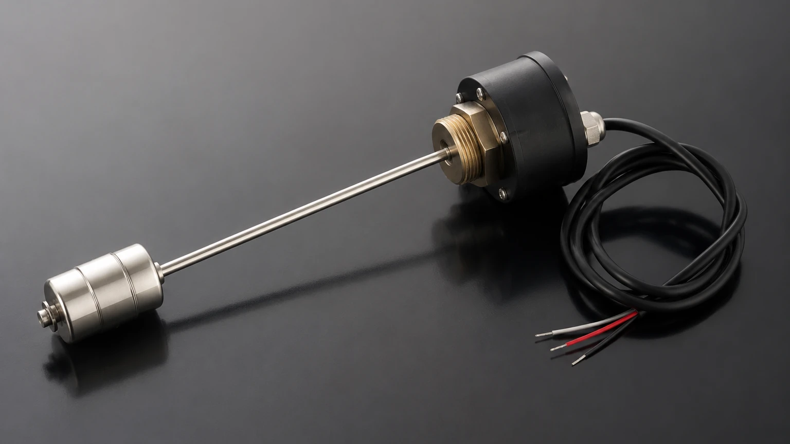
Capacitive sensors are among the most common types of electronic fuel level sensor used in stationary tanks and vehicle fleets. The sensor typically consists of two concentric metal tubes or a single rod and the tank wall, acting as electrodes. As the fuel level rises, it displaces the air between the electrodes. Because fuel has a different dielectric constant (typically 2.0 to 2.2 for diesel) compared to air (1.0), the total capacitance of the circuit changes. The internal electronics convert this change in capacitance into a linear signal, such as 4-20mA or RS485.
Hydrostatic Pressure Measurement
Hydrostatic sensors measure the pressure exerted by the column of liquid above a sensing diaphragm. This pressure is directly proportional to the height of the fuel and its density (P = ρgh). For fuel applications, submersible transmitters or externally mounted pressure sensors are used. These are particularly effective in deep storage tanks where rod-type sensors may be impractical. However, they require accurate density data to maintain precision, as fuel density changes with temperature.
Ultrasonic and Radar (Non-Contact)
Non-contact sensors are mounted at the top of the tank and emit either sound waves (ultrasonic) or electromagnetic waves (radar). The sensor measures the time of flight for the signal to bounce off the fuel surface and return.
- Ultrasonic: Cost-effective but sensitive to temperature fluctuations and vapors in the tank headspace.
- Radar: Highly accurate and unaffected by vapor, pressure, or temperature. High-frequency radar (e.g., 26GHz or 80GHz) is increasingly preferred for industrial fuel depots due to its narrow beam and immunity to internal tank obstructions.
Technical Comparison of Sensor Types
The following table summarizes the performance characteristics of various electronic fuel level sensor technologies to assist in the selection process.
| Technology | Accuracy | Measurement Range | Best Use Case | Limitations |
| :— | :— | :— | :— | :— |
| Capacitive | ±0.5% to ±1% | Up to 3 meters | Vehicle tanks, generators | Sensitive to fuel contamination/water |
| Hydrostatic | ±0.25% to ±0.5% | Up to 20+ meters | Deep underground storage | Requires density compensation |
| Ultrasonic | ±0.25% | 0.3 to 15 meters | Non-volatile fuel storage | Affected by heavy foam or vapor |
| Radar | ±1mm to ±3mm | Up to 30+ meters | High-precision bulk storage | Higher initial capital investment |
Integration and Signal Output
Modern industrial systems require more than just a local display. An electronic fuel level sensor must integrate seamlessly into broader Automation or Telemetry systems. Common output protocols include:
1. Analog (4-20mA / 0-5V): The standard for traditional PLC and SCADA integration. The 4-20mA current loop is particularly robust against electrical noise over long cable runs.
2. Digital (RS485/Modbus): Allows for the transmission of multiple data points, including fuel level, volume, and temperature, over a single pair of wires. This is ideal for multi-tank installations.
3. Wireless (LoRaWAN/NB-IoT): Used for remote fuel tanks (e.g., cell tower backup generators) where wiring is cost-prohibitive.
For comprehensive system design and to explore specific hardware configurations, engineers can visit the Main Page of professional manufacturers like Welk to review product options and application support.
Installation Considerations
To ensure the longevity and accuracy of an electronic fuel level sensor, specific installation protocols must be followed. Failure to account for the physical environment can lead to signal drift or premature sensor failure.
Tank Geometry and Dead Zones
Every sensor has a "dead zone" or "blocking distance" at the top and bottom. For example, an ultrasonic sensor may not be able to measure anything within the first 200mm from its face. This must be accounted for when calculating the total usable volume of the tank. If the tank has internal baffles or heating coils, the sensor must be positioned to avoid these obstructions, particularly when using radar or ultrasonic technologies.
Grounding and Shielding
Fuel tanks are often located in environments with high electromagnetic interference (EMI) from pumps and motors. Using shielded cables and ensuring proper grounding of the sensor housing is essential to prevent signal "jitter." In the case of capacitive sensors, the sensor body must be electrically bonded to the tank if the tank is metallic.
Temperature Compensation
Fuel expands and contracts significantly with temperature changes. A change of 10°C can result in a measurable change in fuel volume even if no fuel has been added or removed. Advanced electronic fuel level sensors include integrated temperature probes (PT100 or PT1000) to provide real-time compensation, ensuring that the reported volume is normalized to a standard temperature (e.g., 15°C).
Limitations and Common Risks
While electronic sensors are highly reliable, they are not immune to environmental and chemical challenges.
* Fuel Contamination: Water is heavier than fuel and settles at the bottom of the tank. In capacitive sensors, water can short-circuit the electrodes or cause massive spikes in readings because the dielectric constant of water (≈80) is much higher than that of diesel (≈2).
* Paraffin Wax Buildup: In cold climates, diesel fuel can "cloud," and paraffin wax may precipitate out. This wax can coat the rods of capacitive sensors or the diaphragms of hydrostatic sensors, leading to sluggish response or inaccuracy.
* Vapor and Condensation: In high-humidity environments, condensation can form on the face of non-contact sensors. While radar can typically see through this, ultrasonic signals may be scattered, leading to a "lost echo" error.
* Chemical Compatibility: Ensure that all wetted parts (316L stainless steel, PTFE, FKM/Viton) are compatible with the specific fuel type, especially biofuels or ethanol-blended gasolines which can be more corrosive than pure petroleum products.
Maintenance and Calibration
Industrial fuel sensors should be checked annually. For hydrostatic and capacitive sensors, this involves a "zero and span" verification. This is done by checking the output when the tank is empty (or the sensor is dry) and comparing it to the output at a known level. Many digital sensors now support remote calibration via software, allowing technicians to adjust offsets without removing the sensor from the tank.
Frequently Asked Questions (FAQ)
Q: Can one electronic fuel level sensor be used for different types of fuel?
A: It depends on the technology. Hydrostatic and capacitive sensors must be recalibrated if you switch from diesel to gasoline because the density and dielectric constants differ. Radar and ultrasonic sensors are generally unaffected by the fuel type, provided the surface reflects the signal properly.
Q: How do I handle fuel foaming during high-speed filling?
A: Foaming can cause ultrasonic sensors to give false high readings. In these cases, a stilling well (a vertical pipe that houses the sensor) should be installed to provide a calm liquid surface for measurement. Alternatively, radar sensors are much more resistant to foam interference.
Q: What is the typical lifespan of an industrial fuel sensor?
A: With proper installation and protection from electrical surges, a high-quality sensor from a manufacturer like Welk typically lasts 5 to 10 years. The primary failure points are usually lightning strikes or severe fuel contamination (water/acid).
Q: Are these sensors safe for use with flammable fuels?
A: Yes, but they must be rated for hazardous areas. Look for certifications such as ATEX, IECEx, or UL Class I, Div 1. These ensure the sensor is either intrinsically safe (limiting the energy to prevent sparks) or explosion-proof (contained in a heavy-duty housing).
By following these engineering guidelines and selecting a sensor matched to the specific demands of the application, facility managers can ensure precise inventory control and protect their critical fuel infrastructure.