Electronic Water Level Sensor
Electronic Water Level Sensor
In the landscape of modern industrial automation, the electronic water level sensor has become an indispensable component for process control and resource management. Moving beyond the limitations of traditional mechanical float switches, electronic sensors provide high-precision data, digital integration, and long-term reliability in demanding environments. Whether used in municipal water treatment, chemical processing, or industrial cooling systems, selecting the correct sensing technology is critical for operational efficiency and safety.
This guide explores the underlying measurement principles of electronic water level sensors, provides technical selection criteria, and outlines best practices for installation and maintenance in professional B2B applications.
Core Measurement Principles
Electronic water level sensors utilize several distinct physical principles to convert the physical height of a liquid into an electrical signal, typically 4-20mA, 0-10V, or digital protocols like Modbus RS485.
Hydrostatic Pressure Measurement
Hydrostatic sensors operate on the principle that the pressure at a specific depth in a static liquid is proportional to the height of the liquid column above it. The relationship is defined by the formula:
*P = ρ × g × h*
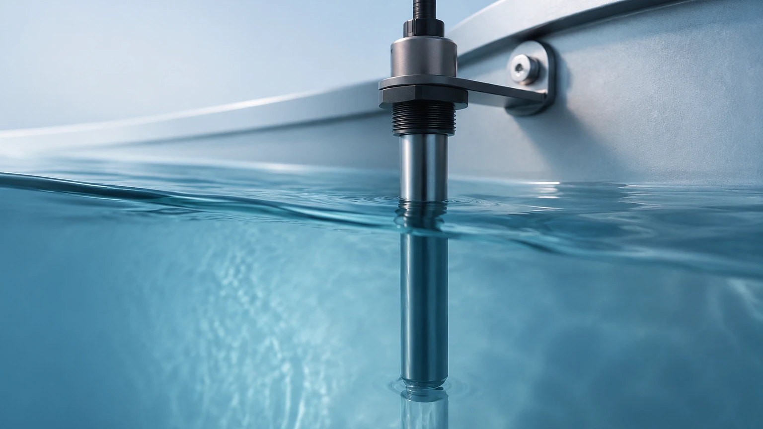
Where *P* is pressure, *ρ* (rho) is the density of the liquid, *g* is the gravitational constant, and *h* is the height of the liquid. A submersible electronic water level sensor typically uses a piezo-resistive or ceramic pressure cell to detect this weight, venting the back of the sensor to atmospheric pressure via a specialized cable to compensate for barometric changes.
Ultrasonic Time-of-Flight
Ultrasonic sensors are non-contact devices that emit high-frequency sound pulses (typically 20 kHz to 200 kHz). These pulses travel through the air, reflect off the water surface, and return to the transducer. By measuring the time-of-flight, the sensor calculates the distance to the water surface. This technology is ideal for applications where the sensor should not touch the media, such as corrosive wastewater or open-channel flow measurement.
Radar (Radio Detection and Ranging)
Radar sensors follow a similar time-of-flight principle but use electromagnetic waves (often in the 26GHz or 80GHz bands) instead of sound. Radar is highly effective in environments with varying temperatures, high pressure, or heavy vapor, as electromagnetic waves are not affected by air density or air temperature fluctuations. For complex industrial setups, radar often provides the highest level of accuracy and reliability.
Capacitive Level Sensing
Capacitive sensors measure the change in electrical capacitance between two electrodes (or one electrode and the tank wall) as the water level rises. Since water has a significantly higher dielectric constant than air, the total capacitance increases linearly with the level. These are often used for point-level detection or continuous measurement in smaller tanks.
Key Selection Criteria for Industrial Applications
Choosing the right electronic water level sensor requires a thorough analysis of the process environment. Engineers should evaluate the following factors before procurement:
1. Media Characteristics: While the focus is water, the presence of chemicals, high salinity, or suspended solids can dictate material choice. For instance, 316L stainless steel is standard, but PTFE or Hastelloy may be required for aggressive media.
2. Accuracy Requirements: Hydrostatic sensors typically offer 0.25% to 0.5% FS (Full Scale) accuracy, while high-frequency radar can achieve ±2mm precision.
3. Tank Geometry and Obstructions: Internal structures like agitators, ladders, or inlet pipes can interfere with non-contact sensors. In such cases, guided wave radar or hydrostatic transmitters are often preferred.
4. Environmental Conditions: Consider the ambient temperature and the potential for foam or steam. Ultrasonic sensors may fail in heavy foam, whereas radar can penetrate it more effectively.
Selection Comparison Table
| Technology | Contact Type | Accuracy | Max Range | Best Use Case |
| :— | :— | :— | :— | :— |
| Hydrostatic | Contact | High (0.25%) | Up to 500m | Deep wells, vented tanks, reservoirs |
| Ultrasonic | Non-contact | Moderate (0.5%) | Up to 15-30m | Open channels, wastewater, sumps |
| Radar | Non-contact | Very High (±2mm) | Up to 100m | Process tanks, high-temp, high-vapor |
| Capacitive | Contact | Moderate | Up to 5m | Small tanks, chemical dosing, oils |
Installation and Commissioning Best Practices
Proper installation is as vital as the technology itself. Even the most advanced electronic water level sensor will provide inaccurate data if poorly positioned.
Positioning and Mounting
* Avoid the Inlet: Never install a sensor directly under the water inlet. The turbulence and force of incoming water will cause signal instability and potential physical damage.
* Stilling Wells: In tanks with high turbulence or agitators, installing the sensor inside a stilling well (a vertical pipe with vent holes) can provide a stable surface for measurement.
* Dead Zones: Non-contact sensors have a "dead zone" or "blocking distance" (typically 0.2m to 0.5m) near the transducer face where measurement is impossible. Ensure the sensor is mounted high enough to avoid this zone during high-level conditions.
Electrical and Signal Integration
* Shielding: Use shielded twisted-pair cables to prevent Electromagnetic Interference (EMI) from high-voltage equipment or Variable Frequency Drives (VFDs).
* Venting: For hydrostatic sensors, ensure the atmospheric vent tube in the cable is not kinked or blocked. Use a desiccant cartridge if the environment is highly humid to prevent internal condensation.
* Calibration: Most modern electronic sensors are factory-calibrated, but field zero-point adjustment is recommended after installation to account for specific mounting heights.
For engineers seeking detailed technical specifications and application-specific support, it is advisable to visit the Main Page to review product options and application support.
Operational Limitations and Challenges
While electronic water level sensors are highly capable, they are not universal solutions. Understanding their limitations prevents field failures.
* Foam and Turbulence: Heavy surface foam can absorb ultrasonic signals, leading to a "loss of echo." In these scenarios, hydrostatic or radar sensors are more resilient.
* Vapor and Condensation: In closed tanks, water vapor can condense on the face of ultrasonic transducers, causing signal drift. Some sensors include "drip-off" designs or heated faces to mitigate this.
* Build-up: In wastewater applications, grease or biological growth can accumulate on contact-based probes. Regular cleaning schedules or switching to non-contact radar can reduce maintenance overhead.
Frequently Asked Questions (FAQs)
Q: Can an electronic water level sensor be used in pressurized tanks?
A: Yes, but the technology matters. A standard vented hydrostatic sensor cannot be used in a pressurized tank because it cannot distinguish between liquid pressure and head pressure. In these cases, a differential pressure (DP) transmitter or a non-contact radar sensor is required.
Q: What is the typical lifespan of a submersible water level sensor?
A: In clean water, a high-quality electronic water level sensor can last 7 to 10 years. In corrosive or high-lightning areas (outdoor reservoirs), the lifespan may be shorter unless proper surge protection and material compatibility are addressed.
Q: How does temperature affect accuracy?
A: Most electronic sensors include internal temperature compensation. However, for ultrasonic sensors, the speed of sound changes with air temperature. If the sensor does not have a built-in temperature probe or an external compensation source, accuracy will decrease as the temperature fluctuates.
Conclusion
The transition to electronic water level sensors offers industrial operators enhanced precision, better data logging, and reduced manual monitoring. By understanding the physics of hydrostatic, ultrasonic, and radar technologies, and by adhering to strict installation guidelines, facilities can ensure long-term reliability in their level measurement systems. When selecting a device, always prioritize the specific constraints of your process environment—such as pressure, temperature, and media consistency—to ensure the chosen sensor delivers the necessary performance. For further technical guidance and a comprehensive range of industrial instruments, consult the professional resources available at the Welk Main Page.